

Electric cabinet lifting device
A lifting device and electric cabinet technology, applied in the field of electric cabinets, can solve problems such as unsteady lifting process, affecting lifting safety, simple structure, etc., and achieve the effect of meeting the needs of use and stable lifting
- Summary
- Abstract
- Description
- Claims
- Application Information
AI Technical Summary
Problems solved by technology
Method used
Image

Examples
Embodiment Construction
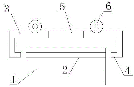
[0009] Such as figure 1 It is a structural schematic diagram of the present invention, a lifting device for an electric cabinet, including a box body 1, a through hole 2 is provided in the box body 1, a boom 3 is arranged above the box body 1, and a boom 3 is arranged at the end of the box body 1. There is a block 4, a telescopic device 5 is arranged inside the boom 3, and a suspension ring 6 is arranged on the boom 3.
[0010] When this electric cabinet lifting device is in use, the position of the boom 3 is controlled by the telescopic device 5, and the block 4 on the boom 3 is inserted into the through hole 2 of the cabinet 1 to fix the cabinet, and then It can be hoisted, and the hoisting is stable to meet the needs of use.
[0011] The above description is only illustrative, rather than restrictive, to the present invention. Those skilled in the art understand that many modifications, changes or the like can be made without departing from the spirit and scope defined by ...
PUM
 Abstract
Description
Claims
Application Information