

Lifting system
A lifting system and lifting seat technology, applied in the direction of hoisting device, spring mechanism, etc., can solve the problems of difficult maintenance, inconvenient operation, complex structure, etc., and achieve the effect of stable work, cost saving and stable lifting
- Summary
- Abstract
- Description
- Claims
- Application Information
AI Technical Summary
Problems solved by technology
Method used
Image

Examples
Embodiment Construction
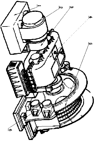
[0014] Such as figure 1 As shown, the object of the present invention is achieved in the following way: a hoisting and hoisting system includes a base 1, and a driving device is fixedly arranged on the base 1, and is characterized in that a reduction box is arranged beside the driving device, and the reduction gear The box is fixed on the ground through a fixed seat, a buffer device is provided between the fixed seat and the ground, a bracket is provided between the driving device and the reduction box, a shield is provided on the bracket, and the driving device passes through a coupling 3 It is directly connected with the reduction box, the other side of the reduction box is provided with a lifting seat 6, and the lifting seat 6 is provided with a wire reel 5, and several steel cables are arranged in the cable, and the output shaft of the reduction box is directly connected to the The input shaft of the wire reel 5 is connected, a reinforcing rib is arranged between the lifti...
PUM
 Abstract
Description
Claims
Application Information