
Uncapping mechanism of test tubes
A test tube cap and test tube technology, applied in the field of medical devices, can solve problems such as difficult functional requirements and no solutions
- Summary
- Abstract
- Description
- Claims
- Application Information
AI Technical Summary
Problems solved by technology
Method used
Image

Examples
Embodiment Construction
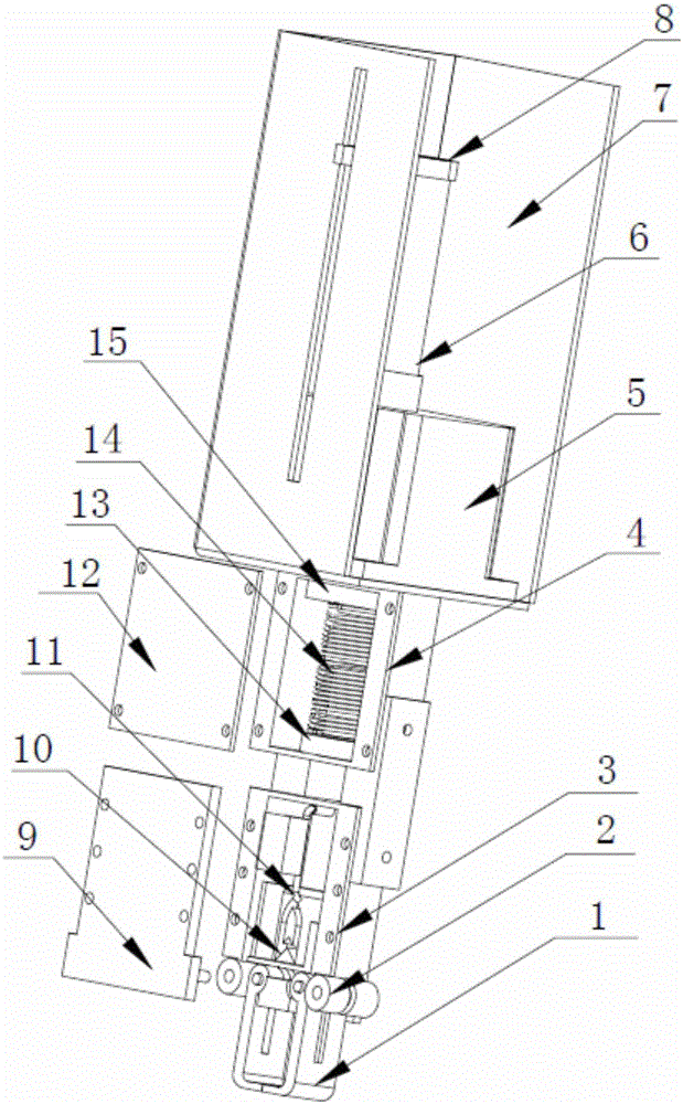
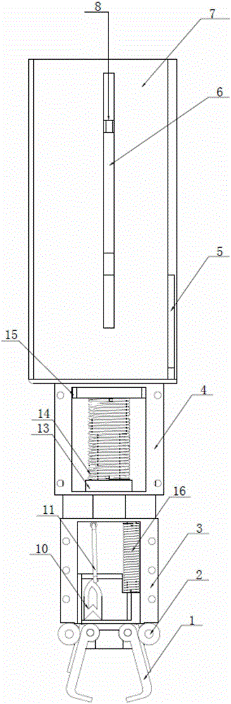
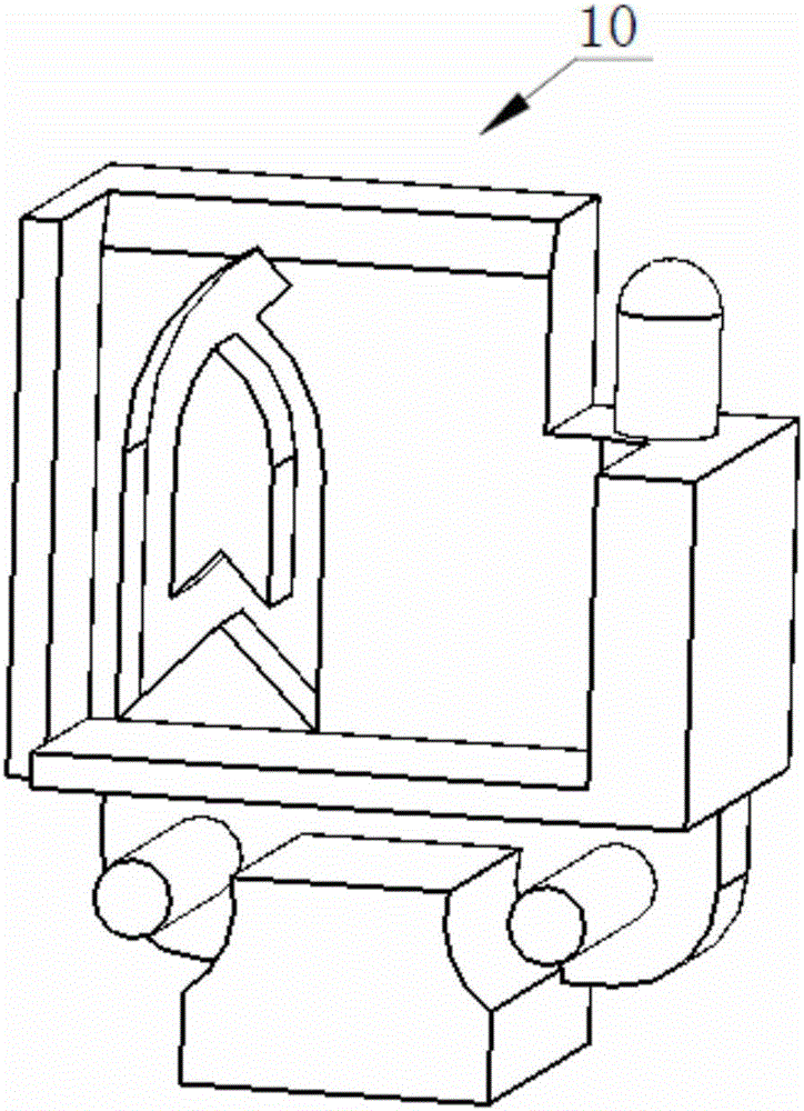
[0021] Such as figure 1 As shown, the test tube cap removal mechanism according to the present invention includes: claw 1, button 2, cover cavity 3, transition cavity 4, linear motor 5, motor screw 6, support sheet metal 7, upper gasket 8, claw Sealing plate 9, claw fixing plate 10, hook 11, transition plate 12, lower gasket 13, first compression spring 14, lead screw nut 15, second compression spring 16.
[0022] Wherein, the test tube capping mechanism has a supporting sheet metal 7, and the interior forms a rectangular accommodation space as a whole. A linear motor 5 is arranged at the bottom of the accommodating space, and the bottom end of the linear motor 5 is fixed on the lower bottom surface of the supporting sheet metal 7 with four fasteners for driving the motor lead screw 6 .
[0023] The upper end of the motor lead screw 6 has an upper gasket 8, and the lower gasket 13 is arranged at the bottom. Wherein the upper gasket 8 is a strip-shaped structure, and one end...
PUM
 Abstract
Description
Claims
Application Information