Machine tool workbench facilitating clamping

A workbench and machine tool technology, applied in the field of machine tools, can solve problems such as poor stability, inability to clamp parts of different sizes, poor practicability, etc., and achieve the effect of improving stability and convenient pressing

Inactive Publication Date: 2021-03-16
QINGYUAN POLYTECHNIC
View PDF0 Cites 0 Cited by
  • Summary
  • Abstract
  • Description
  • Claims
  • Application Information

AI Technical Summary

Problems solved by technology

[0003] At present, when using machine tools to process parts, it is necessary to clamp and fix the parts. However, the existing machine tools have poor stability when clamping parts, and cannot clamp when processing parts of different sizes. Poor, for this reason, we propose a machine tool table that is easy to clamp to solve the above problems

Method used


Image

  • Machine tool workbench facilitating clamping
  • Machine tool workbench facilitating clamping
  • Machine tool workbench facilitating clamping

Examples


Embodiment 1

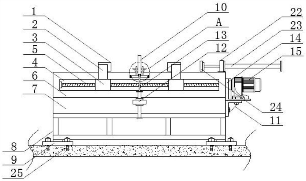
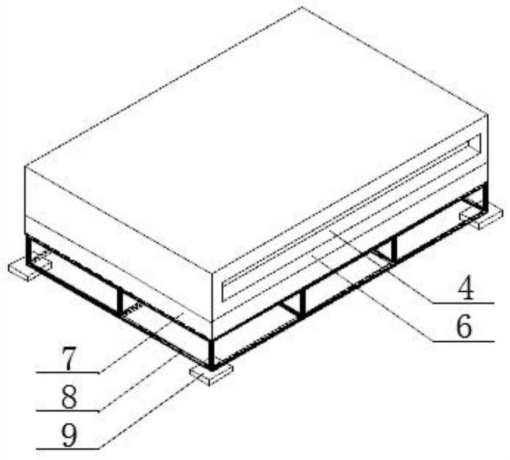
[0029] refer to figure 1 , 2 , 3, 4, a kind of machine tool workbench that is convenient to clamp, comprises bearing platform 7, plays the effect of supporting and fixing, and the upper end of bearing platform 7 is fixed with operating platform 6, is convenient to process parts, and operating platform 6 is provided with empty There are openings 4 on both sides of the cavity, and an adjustment device is provided in the cavity. Two moving plates 3 are arranged on the adjustment device. On both sides of the table 6, two moving blocks 2 are fixed on the upper end of the moving plate 3, and the moving of the moving plate 3 drives the moving block 2 to move, and the two moving blocks 2 are respectively located on both sides of the console 6, and the upper end of the moving block 2 is There is an L-shaped clamping plate 1 fixed on the side, and the movement of the moving block 2 drives the L-shaped clamping plate 1 to move, and the four L-shaped clamping plates 1 correspond to each ...

Embodiment 2

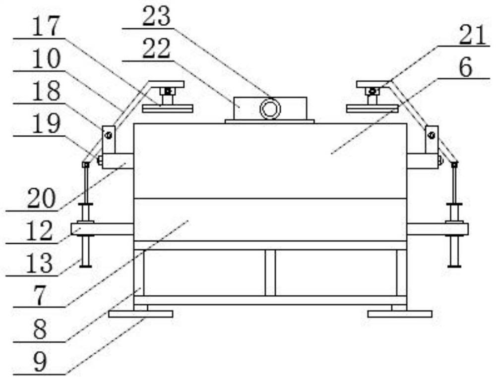
[0033] refer to figure 1 , 2 , 3, 4, 5, a machine tool workbench that is convenient to clamp, includes a bearing platform 7, which plays a role of support and fixation, and the upper end of the bearing platform 7 is fixed with an operation platform 6, which is convenient for processing parts. There is a cavity, openings 4 are provided on both sides of the cavity, an adjustment device is provided in the cavity, and two moving plates 3 are arranged on the adjustment device, and the two ends of the two moving plates 3 respectively pass through the two openings 4 and extend To both sides of the console 6, two moving blocks 2 are fixed on the upper end of the moving plate 3, the moving of the moving plate 3 drives the moving block 2 to move, and the two moving blocks 2 are respectively located on both sides of the operating table 6, and the moving blocks 2 An L-shaped clamping plate 1 is fixed on one side of the upper end, and the movement of the moving block 2 drives the L-shaped...

Embodiment 3

[0038] refer to figure 1 , 2 , 3, 4, 6, a machine tool workbench for easy clamping, including a bearing platform 7, which plays the role of support and fixation, the upper end of the bearing platform 7 is fixed with an operation platform 6, which is convenient for processing parts, and the operation platform 6 is equipped with There is a cavity, openings 4 are provided on both sides of the cavity, an adjustment device is provided in the cavity, and two moving plates 3 are arranged on the adjustment device, and the two ends of the two moving plates 3 respectively pass through the two openings 4 and extend To both sides of the console 6, two moving blocks 2 are fixed on the upper end of the moving plate 3, the moving of the moving plate 3 drives the moving block 2 to move, and the two moving blocks 2 are respectively located on both sides of the operating table 6, and the moving blocks 2 An L-shaped clamping plate 1 is fixed on one side of the upper end, and the movement of the...


PUM


Abstract

The invention discloses a machine tool workbench facilitating clamping. The workbench comprises a bearing table, an operation table is fixed to the upper end of the bearing table, a cavity is formed in the operation table, openings are formed at the two sides of the cavity, an adjusting device is arranged in the cavity, and two moving plates are arranged on the adjusting device; and the two ends of the two moving plates penetrate through the two openings correspondingly and extend to the two sides of the operation table, two moving blocks are fixed to the upper ends of the moving plates and located at the two sides of the operation table correspondingly, L-shaped clamping plates are fixed to one sides of the upper ends of the moving blocks, and the four L-shaped clamping plates correspondto one another. According to the workbench, the problem that parts of different sizes are inconvenient to clamp and fix is solved, meanwhile, the problem that the stability of the parts is poor is solved, the situation that the parts are wasted due to machining deviation caused by movement of the parts is avoided, the stability of the parts is improved, and meanwhile the machining efficiency is improved.

Description

technical field [0001] The invention relates to the technical field of machine tools, in particular to a conveniently clamped machine tool workbench. Background technique [0002] A machine tool refers to a machine that manufactures a machine, also known as a machine tool or a tool machine, and is customarily referred to as a machine tool. Generally divided into metal cutting machine tools, forging machine tools and woodworking machine tools. There are many ways to process mechanical parts in modern machinery manufacturing: in addition to cutting, there are also casting, forging, welding, stamping, extrusion, etc. The final machining is done by cutting on the machine tool. Machine tools play an important role in the modernization of the national economy. [0003] At present, when using machine tools to process parts, it is necessary to clamp and fix the parts. However, the existing machine tools have poor stability when clamping parts, and cannot clamp when processing par...

Claims


Application Information

Patent Timeline
Patent Type & Authority Applications(China)
IPC IPC(8): B23Q1/25B23Q3/08
CPCB23Q1/25B23Q3/08
Inventor 卜慧敏卜倩雯曹丹
Owner QINGYUAN POLYTECHNIC
Why Eureka
Try Eureka