A spinner structure

A spinner and support structure technology, applied in the direction of drill pipe, casing, drill pipe, etc., can solve the problems of drilling tool thread damage, shaking, and the spinner cannot be automatically adjusted up and down, so as to improve clamping and prevent The effect of the buckle

Active Publication Date: 2022-06-28
SICHUAN HONGHUA PETROLEUM EQUIP
View PDF13 Cites 0 Cited by
  • Summary
  • Abstract
  • Description
  • Claims
  • Application Information

AI Technical Summary

Problems solved by technology

[0004] At present, most iron drillers use articulated spinners. During the spinner operation, for drilling tools with different diameters, the spinner center of the spinner will deviate. There will be shaking during the process, so misalignment is prone to occur during the buckle, which makes the efficiency of the buckle low
Secondly, the spinner cannot be automatically adjusted up and down with the up and down action, which may easily cause damage to the thread of the drilling tool

Method used


Image

  • A spinner structure
  • A spinner structure
  • A spinner structure

Examples


Embodiment 1

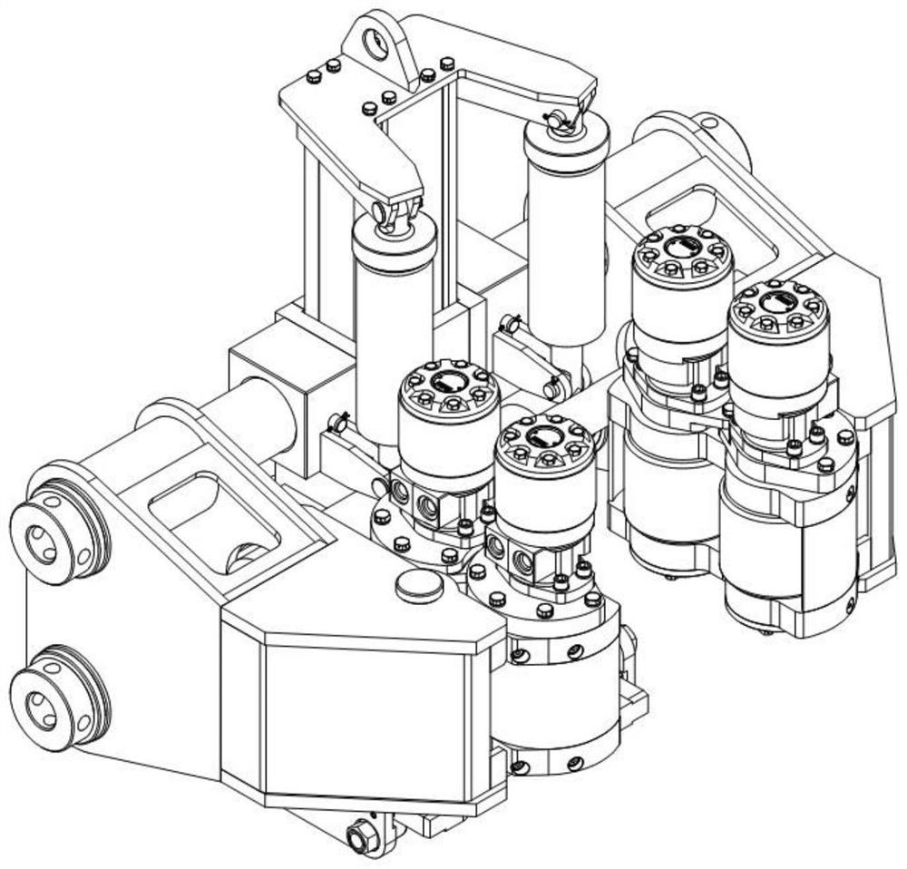
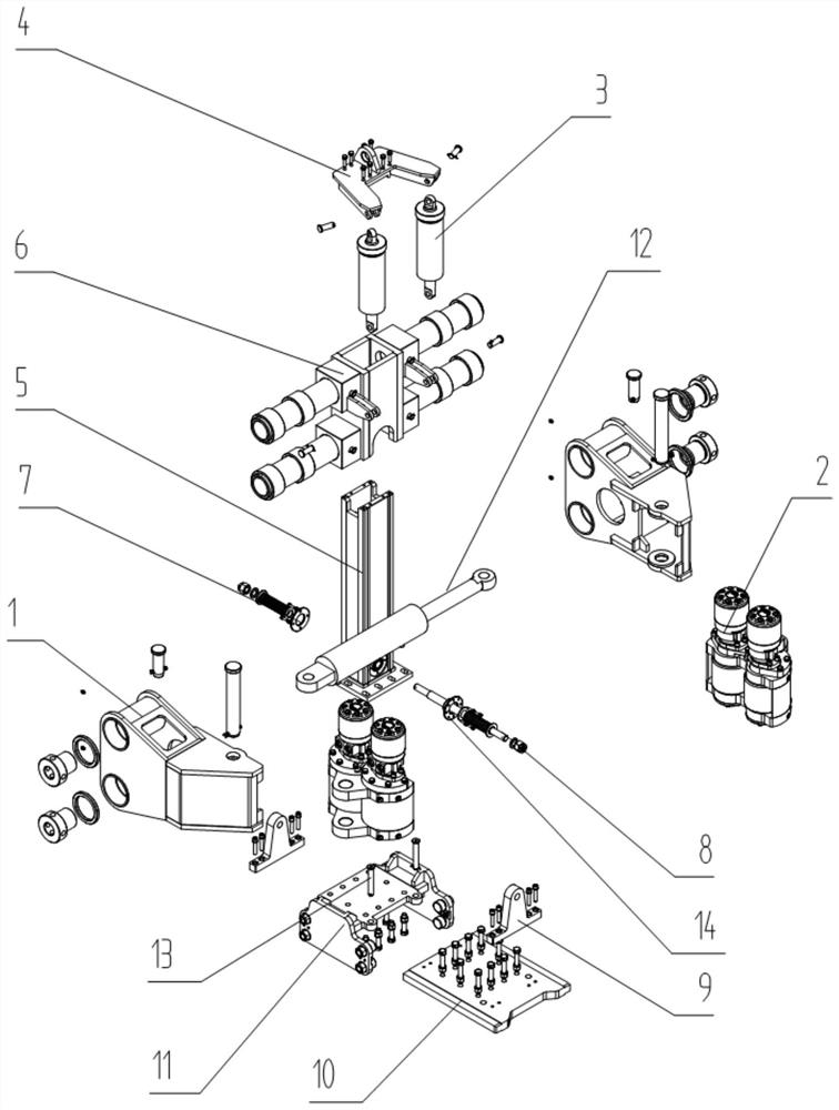
[0051] A spinner structure such asfigure 1 As shown, it includes a seat body on which a suspension assembly 3 is arranged, a support frame 6 is also arranged on the seat body, and hooks 1 are arranged on both sides of the support frame 6, and the hooks 1 A rotary wheel assembly 2 is provided on the hook, the hook 1 can move along the support frame 6, and a driving device 12 is also arranged between the hooks 1 to control the displacement of the hook 1;

[0052] The seat body is equipped with a guide frame 5 , the support frame 6 is sleeved on the guide frame 5 , the support frame 6 can slide up and down along the guide frame 5 , and one end of the suspension assembly 3 is assembled and connected with the guide frame 5 , the other end is assembled and connected with the support frame 6;

[0053] The rotary wheel assembly includes a support structure on which a power device 21 is arranged, the power device 21 is connected with a rotating shaft 23, and a rotary wheel 22 is fixed ...

Embodiment 2

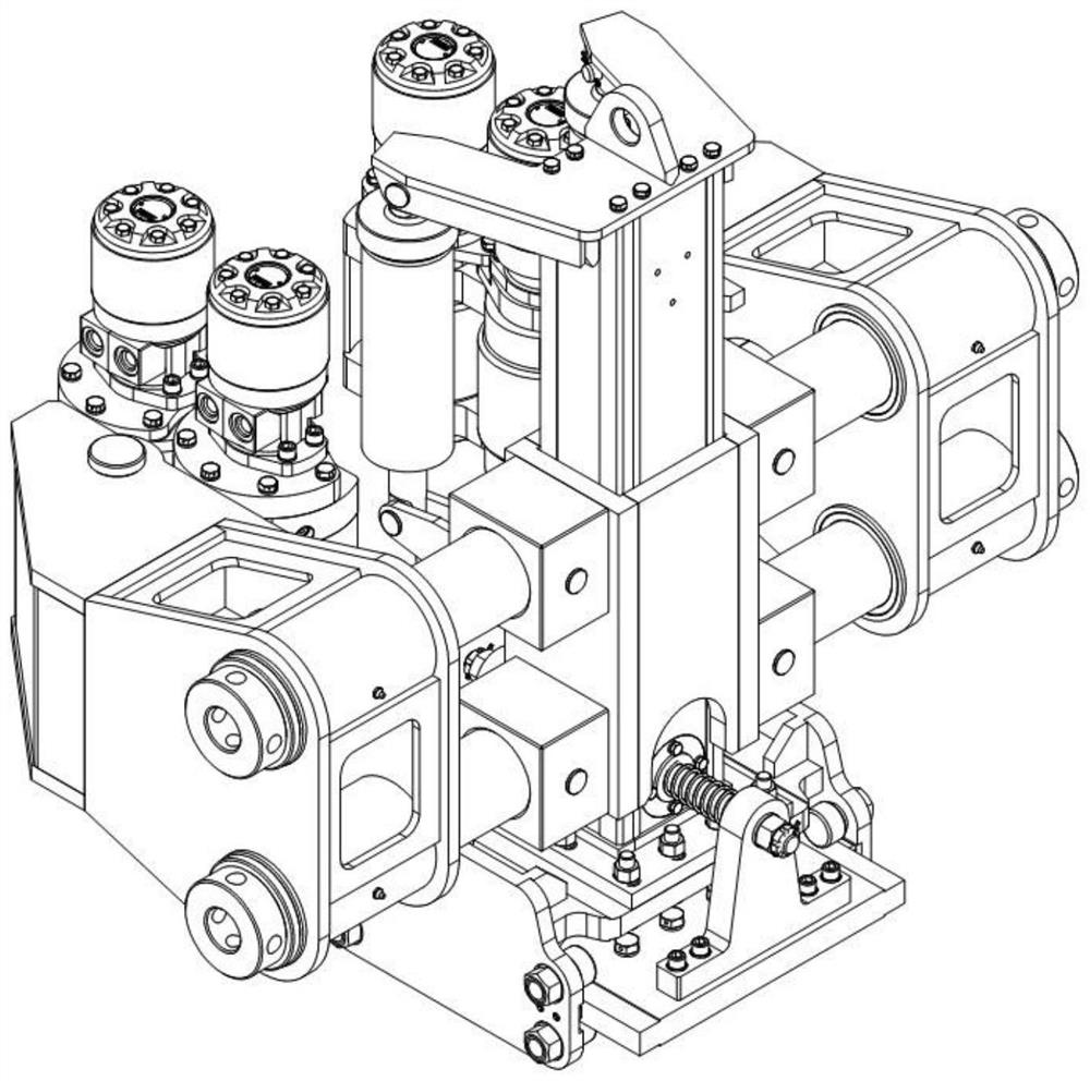
[0067] On the basis of Embodiment 1, as a more specific design, two sets of bearings 111 or three sets of bearings 111 are respectively provided on both sides of the lower part of the pulley 11 , and each set of bearings 111 is two bearings 111 installed up and down. The upper and lower side walls of the mounting plate 10 are provided with guide rail grooves.

[0068] As a more specific design, the bearing sets on both sides are arranged symmetrically to ensure the uniformity of the force and the stability of the overall pulley. In a more specific design, the guide rail grooves are provided on the upper and lower side walls on both sides of the pulley mounting plate 10 . More specifically, after this design, the thickness of the position where the guide groove is located is smaller than the thickness of the chute mounting plate 10 .

Embodiment 3

[0070] Based on the designs of Embodiments 1 and 2, further design is made for the assembly relationship between the guide frame 5, the pulley 11 and the pulley mounting plate 10. The side of the pulley 11 is an inverted "concave" structure. The top side wall of the pulley 11 is provided with a plurality of through holes, and the bottom of the guide frame 5 is provided with a plurality of through holes, which are assembled and fixed by bolts. Here, the bottom of the guide frame 5 is provided with assembling wings. In addition, a bearing 111 and a friction block 112 are provided on the inner side of the side wall of the pulley 11 , and are assembled with the pulley mounting plate 10 accordingly. The pulley assembly plate 10 is provided with a plurality of through holes, which are assembled with the clamp body through bolts. The limit assembly can be realized by the limit pin 13 between the pulley assembly plate 10 and the pulley 11 .


PUM


Abstract

The invention discloses a spinner structure, which belongs to the field of oil drilling equipment; the device includes a base body, a suspension assembly is arranged on the base body, and a support frame is arranged on the base body, and the support frame There are hooks on both sides, the hooks are provided with a rotary wheel assembly, the hooks can move along the support frame, and a driving device is also arranged between the hooks to control the displacement of the hooks; the seat The body is equipped with a guide frame, the support frame is sleeved on the guide frame, the support frame can slide up and down along the guide frame, and the two ends of the suspension assembly are assembled and connected with the guide frame and the support frame respectively; one of the present invention This kind of spinner structure can adjust the clamping distance through the hook through the driving device to solve the clamping problem of drilling tools with different diameters. Through this structure, the clamping of drilling tools with different diameters / sizes is effectively improved, and the drilling efficiency is improved effectively. The efficiency of making up and breaking down of the tool.

Description

technical field [0001] The invention relates to a spinner structure, belonging to the field of oil drilling equipment. Background technique [0002] In the process of oil and gas field drilling, it is necessary to make several times of buckling and unbuckling of drilling tools at the wellhead. Traditional hydraulic power tongs have many disadvantages, such as time-consuming, labor-intensive, low work efficiency and high degree of danger, which can no longer meet the normal work requirements. The iron drill is a kind of automatic turnbuckling equipment. Its appearance greatly reduces the drilling intensity and improves the operation efficiency and safety. The spinner is one of the main working parts of the iron driller. The iron driller can be divided into two parts during work. First, the spinner spins, and then the clamp body punches the drill joint, and the spinner adjusts the iron. For the driller, the whole thread is screwed in, and the twisting work takes up a lot of w...

Claims


Application Information

Patent Timeline
Patent Type & Authority Patents(China)
IPC IPC(8): E21B19/16
CPCE21B19/161E21B19/163
Inventor 许月刚柴俊卿王麟赵敏贤
Owner SICHUAN HONGHUA PETROLEUM EQUIP
Why Eureka
Try Eureka