Eureka AIR delivers breakthrough ideas for toughest innovation challenges, trusted by R&D personnel around the world.

Device for testing electrochemical performance of energy storage type photo-generated anode

A raw anode and electrochemical technology, which is applied in the field of devices for testing the electrochemical performance of energy-storage photo-generated anodes, can solve problems such as light source loss, error, and easy deviation in the experimental process, and achieve the effect of improving experimental efficiency

Active Publication Date: 2021-10-15
GUANGZHOU SOUNDWEL SCI & TECH CO LTD
View PDF5 Cites 0 Cited by
  • Summary
  • Abstract
  • Description
  • Claims
  • Application Information

AI Technical Summary

Problems solved by technology

[0002] With the continuous development of optoelectronic materials in recent years, some materials with excellent optoelectronic properties have been applied in the field of metal anti-corrosion cathodic protection. When testing chemical properties, it is necessary to combine multiple plates to build an experimental device. The following problems exist in the process: electrodes and salt bridges cannot fix their positions when they are immersed in the electrolyte, and deviations are prone to occur during the experiment. Shaking will bring unnecessary errors to the entire experimental test. When testing the performance of the energy storage type photo-generated anode, it is inconvenient to control the duration of the light source on and off, and unnecessary losses caused by repeated switching of the light source in a short period of time, etc.

Method used


Image

  • Device for testing electrochemical performance of energy storage type photo-generated anode
  • Device for testing electrochemical performance of energy storage type photo-generated anode
  • Device for testing electrochemical performance of energy storage type photo-generated anode

Examples


Embodiment Construction

[0020] This part will describe the specific embodiment of the present invention in detail, and the preferred embodiment of the present invention is shown in the accompanying drawings. Each technical feature and overall technical solution of the invention, but it should not be understood as a limitation on the protection scope of the present invention.

[0021] In the description of the present invention, it should be understood that the orientation descriptions, such as up, down, front, back, left, right, etc. indicated orientations or positional relationships are based on the orientations or positional relationships shown in the drawings, and are only In order to facilitate the description of the present invention and simplify the description, it does not indicate or imply that the device or element referred to must have a specific orientation, be constructed and operated in a specific orientation, and thus should not be construed as limiting the present invention.

[0022] I...


PUM


Abstract

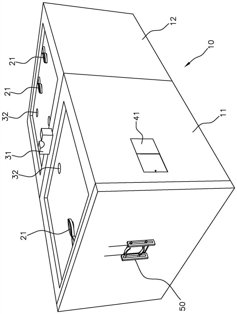
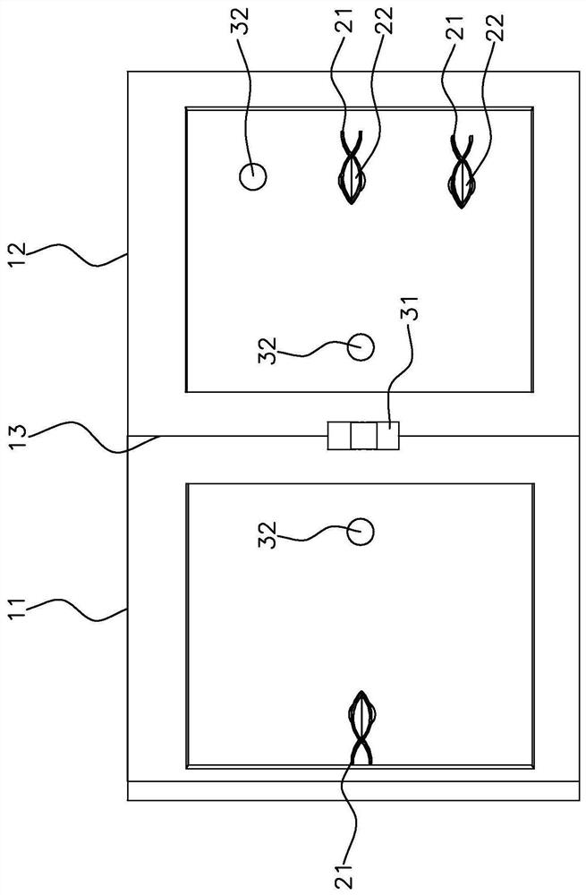
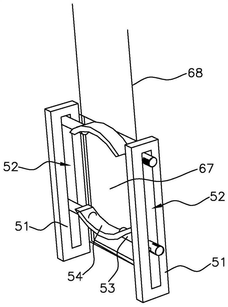
The invention discloses a device for testing the electrochemical performance of an energy storage type photo-generated anode, and relates to the technical field of electrochemical property testing. The device comprises a box body, a plurality of electrode fixing assemblies and a shutter assembly, wherein the box body comprises a first groove and a second groove, the first groove and the second groove are respectively provided with a through hole for a salt bridge to penetrate through, and a salt bridge placement rack is arranged between the box bodies, and is used for fixing a salt bridge; the first groove and the second groove are both provided with the electrode fixing assemblies, and each electrode fixing assembly comprises a clamp with two clamping arms and is used for clamping an electrode; and the shutter assembly comprises a light barrier used for shielding a light source, a guide rail piece allowing the light barrier to slide and a driving unit used for controlling the light barrier to slide along the guide rail piece, and the driving unit drives the light barrier to slide, so that opening or closing of the light barrier is achieved, and the light source is enabled to pass through or be shielded. According to the embodiment of the invention, errors can be reduced, and light input and light-shade period can be controlled.

Description

technical field [0001] The invention relates to the technical field of electrochemical property testing, in particular to a device for testing the electrochemical properties of an energy storage type photogenerated anode. Background technique [0002] In recent years, with the continuous development of optoelectronic materials, some materials with excellent optoelectronic properties have been applied in the field of metal anti-corrosion cathodic protection. When testing the electrochemical properties of photo-generated anode nano-films, it is necessary to combine multiple plates to build experimental devices. , there are the following problems in this process: the electrodes and salt bridges cannot fix their positions when they are immersed in the electrolyte, they are prone to offset during the experiment, and the shaking of the beaker and electrodes will bring unnecessary errors to the entire experimental test. When the performance of the energy-type photo-generated anode ...

Claims


Application Information

Patent Timeline
Patent Type & Authority Applications(China)
IPC IPC(8): G01N27/30
CPCG01N27/30
Inventor 李建三黄祥琪
Owner GUANGZHOU SOUNDWEL SCI & TECH CO LTD
Why Eureka
Eureka Blog
Learn More