Efficient integral formwork

A formwork, integrated technology, applied in the direction of formwork/formwork/work frame, connection parts of formwork/formwork/work frame, and on-site preparation of building components, which can solve problems such as troublesome construction, immovability, and complicated use. , to achieve the effect of quick and simple installation, enhanced transfer shape, and strong stability

Inactive Publication Date: 2016-12-14
河南林艺塑料科技有限公司
View PDF4 Cites 5 Cited by
  • Summary
  • Abstract
  • Description
  • Claims
  • Application Information

AI Technical Summary

Problems solved by technology

[0002] Many walls today are formed by pouring concrete into the wall support formwork. The traditional wall support formwork is generally connected together by connecting fasteners to form the forming surface of the wall, but the existing formwork is spliced ​​up and down. Usually, the plane is directly aligned with the plane, and complex joints are used for positioning. The opposite holes are respectively set on the opposite templates, and the tension tubes concentric with the holes are set between the two templates. The tension tubes are internally stretched, but in When punching and stretching, the two holes need to be positioned concentrically, which is troublesome to construct, and the position of the hole cannot be moved after the hole is punched, and the versatility is poor. To prevent the deformation of the formwork, and the tensile and compressive resistance of the formwork are realized through a special structure, the structure is complex and the versatility is poor

Method used


Image

  • Efficient integral formwork
  • Efficient integral formwork
  • Efficient integral formwork

Examples


Embodiment Construction

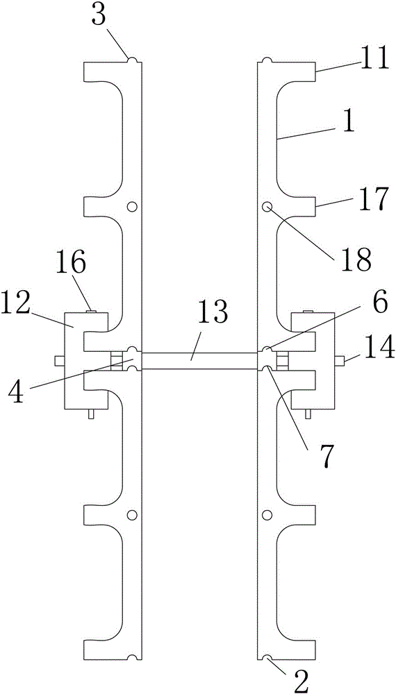
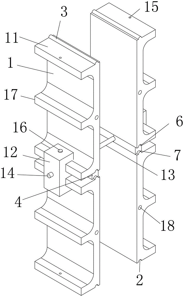
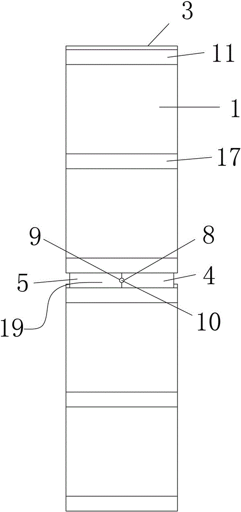
[0018] The specific implementation manners of the present invention will be described in further detail below in conjunction with the accompanying drawings.

[0019] Depend on Figure 1 to Figure 12 Given, the technical solution of the present invention is to include templates 1 that are butted up and down sequentially, the opposite surfaces of the two templates 1 that are connected up and down are respectively provided with a longitudinal first groove 2 and a first protrusion 3, and the upper and lower two butt joints Between the formwork 1 of the template 1, a tie hole opposite block 19 is set, and the tie hole opposite block 19 includes a first opposite block 4 and a second opposite block 5, and the first opposite block 4 and the second pair The upper and lower end surfaces of the block 5 are respectively provided with a second protrusion 6 cooperating with the first groove 2 and a second groove 7 cooperating with the first protrusion 3, the first opposing block 4 and the s...


PUM


Abstract

The invention provides an efficient integral formwork. The efficient integral formwork is characterized in that longitudinal first grooves are respectively formed in opposite surfaces of two formworks connected with each other in the up-down direction, longitudinal first protrusions are respectively arranged on the opposite surfaces of two formworks, tie piece hole opposition blocks are arranged between the two formworks butted to each other in the up-down direction and comprise first opposition blocks and second opposition blocks, second protrusions which are matched with the first grooves are respectively arranged on the upper and lower end surfaces of the first opposition blocks and the second opposition blocks, second grooves which are matched with the first protrusions are respectively formed in the upper and lower end surfaces of the first opposition blocks and the second opposition blocks, transverse first arc-shaped holes and transverse second arc-shaped holes are respectively formed in butted surfaces of the first opposition blocks and the second opposition blocks and are butted to one another to form tie piece holes, tie piece tubes which are concentric with the tie piece holes are arranged between the two opposite tie piece hole opposition blocks, the outer diameters of the tie piece tubes are larger than the sizes of the tie piece holes, tie pieces are penetratingly arranged in the tie piece tubes, and two ends of each tie piece penetrate the corresponding tie piece holes. The efficient integral formwork has the advantage that problems of complicated tensile-resistant and compression-resistant structures of formworks in the prior art, trouble in positioning tie via holes, invariability of the positioned tie via holes and poor transferability can be effectively solved by the aid of the efficient integral formwork.

Description

technical field [0001] The invention relates to the field of building wall pouring, in particular to a high-efficiency integrated formwork. Background technique [0002] Many walls today are formed by pouring concrete into the wall support formwork. The traditional wall support formwork is generally connected together by connecting fasteners to form the forming surface of the wall, but the existing formwork is spliced ​​up and down. Usually, the plane is directly aligned with the plane, and complex joints are used for positioning. The opposite holes are respectively set on the opposite templates, and the tension tubes concentric with the holes are set between the two templates. The tension tubes are internally stretched, but in When punching and stretching, the two holes need to be positioned concentrically, which is troublesome to construct, and the position of the hole cannot be moved after the hole is punched, and the versatility is poor. To prevent the deformation of th...

Claims


Application Information

Patent Timeline
Patent Type & Authority Applications(China)
IPC IPC(8): E04G11/08E04G17/00
CPCE04G11/08E04G17/00
Inventor 郭振杉郭二川
Owner 河南林艺塑料科技有限公司
Why Eureka
Try Eureka