
A self-checking electronic current transformer and its manufacturing method

A current transformer, self-calibration technology, applied in the direction of inductor, voltage/current isolation, transformer/inductor coil/winding/connection, etc. Interference and other problems, to achieve the effect of improving long-term stability and accuracy, fast and small current self-calibration

Active Publication Date: 2019-06-28
CHINA ELECTRIC POWER RES INST +1
View PDF7 Cites 0 Cited by
  • Summary
  • Abstract
  • Description
  • Claims
  • Application Information

AI Technical Summary

Problems solved by technology

[0003] Electronic current transformers have disadvantages such as low accuracy, susceptibility to interference, and poor long-term stability. It is difficult to realize high-current up-current calibration at the substation site, and it is also difficult to perform power-off maintenance.

Method used


Image

  • A self-checking electronic current transformer and its manufacturing method
  • A self-checking electronic current transformer and its manufacturing method
  • A self-checking electronic current transformer and its manufacturing method

Examples


Embodiment Construction

[0019] Exemplary embodiments of the present invention will be described in more detail below with reference to the accompanying drawings. Although exemplary embodiments of the present invention are shown in the drawings, it should be understood that the invention may be embodied in various forms and should not be limited to the embodiments set forth herein. Rather, these embodiments are provided for more thorough understanding of the present invention, and to fully convey the scope of the present invention to those skilled in the art.

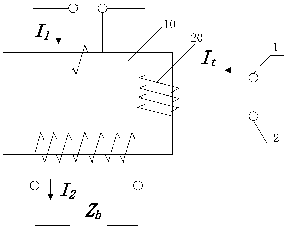
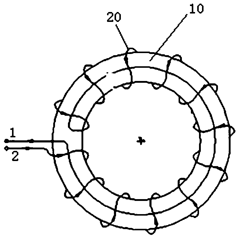
[0020] According to one aspect of the present invention, an electronic current transformer with a new structure is provided to solve the problem that the accuracy of the existing electronic current transformer is unstable and the on-site large current calibration is difficult to realize. Such as figure 1 As shown, an electronic current transformer includes Rogowski coils (such as Rogowski air-core coils) or iron core coils (such as LPCT), whic...


PUM


Abstract

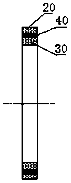
The invention relates to the field of electrical measurement, in particular to a self-checking electronic current transformer which comprises a Rogowski coil or iron core coil. Self-checking coils are uniformly winded on a non-ferromagnetic framework of the Rogowski coil or an iron core framework of the iron core coil. A group of self-checking coils are additionally arranged on a coil framework structure of an original electronic current transformer, and on-site rapid low-current self-checking and online monitoring functions of the electronic current transformer can be achieved, so that long-term stability and accuracy of the electronic current transformer are improved.

Description

technical field [0001] The invention relates to the field of electrical measurement, in particular to an electronic current transformer and a manufacturing method thereof. Background technique [0002] Currently, there are three types of electronic current transformers that are relatively mature in the market: Rogowski coils (Rogowski Coil), low power core coils (LPCT) and all-fiber optic current transformers. These three types of electronic current transformers all have shortcomings such as difficulty in on-site calibration and poor long-term stability and reliability. According to the statistics in the "Research Report on Application of Electronic Transformers" issued by China Electric Power Research Institute, since it was put into operation in 2000, electronic current transformers with a voltage level of 110kV and above in the State Grid Corporation's system have failed 155 times, and the failure rate is More than a hundred times that of traditional current transformers...

Claims


Application Information

Patent Timeline
Patent Type & Authority Patents(China)
IPC IPC(8): H01F38/30H01F27/28H01F27/32G01R15/18
CPCG01R15/18H01F27/2828H01F27/324H01F38/30
Inventor 叶国雄童悦刘彬刘翔黄华胡蓓邓小聘万罡熊俊军代静汪英英吴永康
Owner CHINA ELECTRIC POWER RES INST
Learn More