
A multi-sensor online monitoring system for water pump operation status

A running state, multi-sensor technology, applied in pump testing, instrumentation, pump control, etc., can solve the problems of drainage pipeline backflow, failure to realize automatic control, limited flood discharge capacity of drainage pipeline, etc., and achieve the effect of ensuring smooth flow of water

Active Publication Date: 2021-03-16
新疆河润科技股份有限公司
View PDF9 Cites 0 Cited by
  • Summary
  • Abstract
  • Description
  • Claims
  • Application Information

AI Technical Summary

Problems solved by technology

[0002] In low-lying areas such as bridge openings, in addition to conventional drainage pipes, pumps need to be installed to facilitate rapid drainage when water accumulation occurs in low-lying areas. Most of the existing water pumps are manually controlled. When starting on site, automatic control cannot be realized. Secondly, due to the limited flood discharge capacity of drainage pipes in a short period of time during heavy rain, the phenomenon of "backflow" often occurs in drainage pipes in low-lying areas, that is, floods discharged into drainage pipes in other areas will flow from low-lying areas. The drainage pipes spray out, which intensifies the drainage pressure in low-lying areas. In addition, the drainage outlet may be blocked by garbage and sundries during the drainage process. bring great inconvenience

Method used


Image

  • A multi-sensor online monitoring system for water pump operation status
  • A multi-sensor online monitoring system for water pump operation status
  • A multi-sensor online monitoring system for water pump operation status

Examples


Embodiment Construction

[0015] In order to make the purpose, technical solutions and advantages of the embodiments of the present invention clearer, the technical solutions in the embodiments of the present invention will be clearly and completely described below in conjunction with the drawings in the embodiments of the present invention. Obviously, the described embodiments It is a part of embodiments of the present invention, but not all embodiments. Based on the embodiments of the present invention, all other embodiments obtained by persons of ordinary skill in the art without creative efforts fall within the protection scope of the present invention.

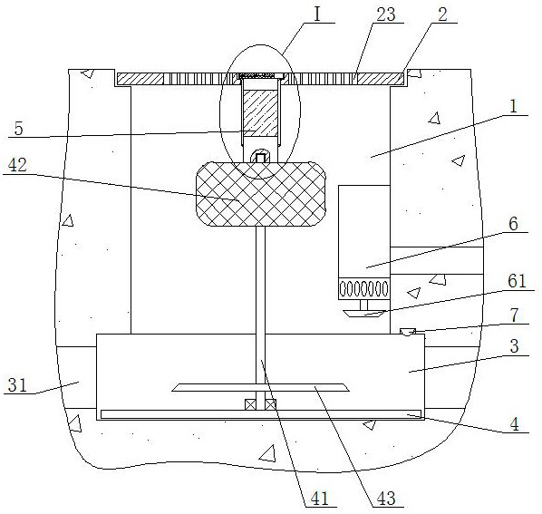
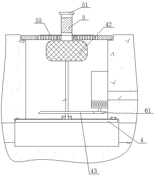
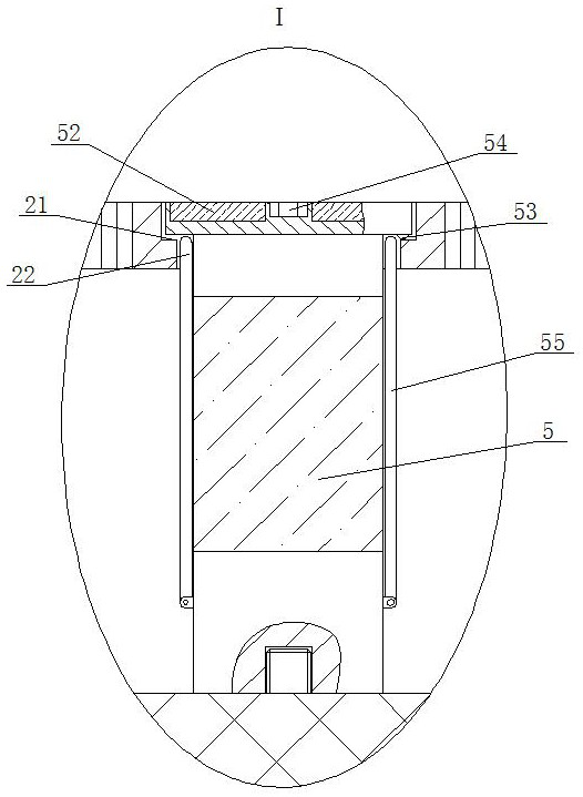
[0016] A multi-sensor online monitoring system for the running state of a water pump, as shown in the figure, includes a well 1 and a well cover 2 placed at its opening. The side walls of the wellway 1 are connected, the diameter of the well cover 2 is larger than the diameter of the wellway 1 and smaller than the outer diameter of the first annul...


PUM


Abstract

The invention discloses a multi-sensor water pump running state online monitoring system. The system comprises a hoistway and a well lid body placed at an opening of the hoistway. A second annular groove is formed in the bottom of the hoistway; the bottom surface of the second annular groove is flush with the bottom surface of the hoistway; a plurality of blow-off pipes are fixedly mounted on theperipheral side wall of the second annular groove; a water stop plate is arranged at the bottom of the second annular groove; a sensing device for sensing the position of the water stop plate is arranged in the second annular groove; a vertical rod is installed in the center of the top face of the water stop plate through a bearing, a buoy is fixedly installed at the top end of the vertical rod, awarning light bar is installed on the top face of the buoy through threads, a groove is formed in the top face of the well lid, a through hole is formed in the bottom face of the groove, and a protective cover is placed in the groove. The top end of the warning light bar penetrates through the through hole and is fixedly connected with the bottom surface of the protective cover. The system integrates multiple functions of automatic water pumping, warning and light emitting, backward flowing prevention and well lid theft prevention, the online monitoring function is achieved through communication of multiple sensors and a remote computer, and the system is a novel automatic water pump with the online monitoring function.

Description

technical field [0001] The invention belongs to the field of automatic control and on-line monitoring of water pumps, in particular to a multi-sensor on-line monitoring system of water pump running states. Background technique [0002] In low-lying areas such as bridge openings, in addition to conventional drainage pipes, pumps need to be installed to facilitate rapid drainage when water accumulation occurs in low-lying areas. Most of the existing water pumps are manually controlled. When water accumulation occurs, special personnel must be arranged When starting on site, automatic control cannot be realized. Secondly, due to the limited flood discharge capacity of the drainage pipes in a short period of time during heavy rain, the phenomenon of "backflow" often occurs for the drainage pipes in low-lying areas, that is, the flood discharged into the drainage pipes in other areas will flow from the low-lying areas. The drainage pipes spray out, which intensifies the drainage ...

Claims


Application Information

Patent Timeline
Patent Type & Authority Patents(China)
IPC IPC(8): H04Q9/00G08B5/36F04B49/10F04B51/00
CPCF04B49/10F04B51/00G08B5/36H04Q9/00
Inventor 王宏志许为民房海勇钟真银
Owner 新疆河润科技股份有限公司
Learn More