Switch of electric appliance provided with electrical heating element and electric appliance

A technology of electric heating elements and switches, applied in electric switches, electrical elements, circuits, etc., can solve the problems of virtual connection, complexity, and unprotected switches.

Inactive Publication Date: 2016-12-14
朱佳音
View PDF4 Cites 0 Cited by
  • Summary
  • Abstract
  • Description
  • Claims
  • Application Information

AI Technical Summary

Problems solved by technology

[0002] Existing stoves, heaters, household appliances, etc. in the world have switch failures. To replace them, it is necessary to disassemble the whole device, connect the internal wiring, and replace the switch, which is relatively complicated.
If the switch circuit is replaced by non-professionals, if the installation is defective, it will easily lead to accidents such as short circuit and false connection in the future
In addition, in the prior art, the side of the above-mentioned switch facing the inner side of the electrical appliance is not protected. Once the temperature inside the electrical appliance is too high, the non-metallic components in the switch may be damaged

Method used


Image

  • Switch of electric appliance provided with electrical heating element and electric appliance
  • Switch of electric appliance provided with electrical heating element and electric appliance
  • Switch of electric appliance provided with electrical heating element and electric appliance

Examples


Embodiment 1

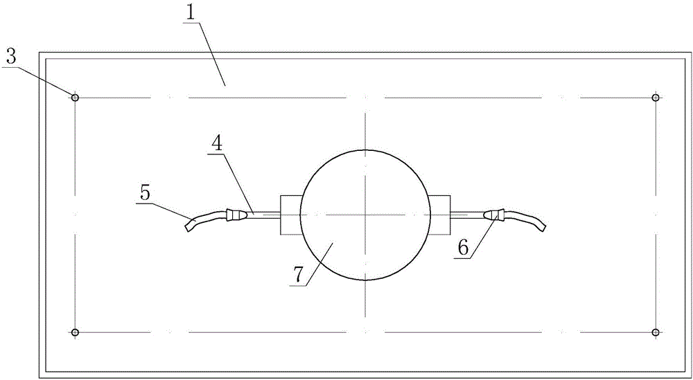
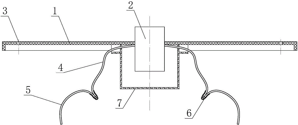
[0030] figure 1 It is the front view of the switch of embodiment 1; figure 2 Yes figure 1 Cutaway view.

[0031] In the figure, the meaning of each reference sign is as follows:

[0032] 1. Switch mounting plate; 2. Switch body; 3. Mounting hole; 4. Class A conductor; 5. Class B conductor; 6. Insulation connection cap; 7. Flame retardant box.

[0033] A switch for an electrical appliance with electric heating elements, comprising a switch mounting plate 1, a switch body 2 is mounted on the switch mounting plate 1, and the switch mounting plate 1 is provided with a plurality of switches for mounting the switch mounting plate 1 in a detachable manner Mounting hole 3 on the outer wall of the appliance.

[0034] By setting the switch mounting plate 1 to be detachably installed on the outer wall of the appliance, when the switch fails or is damaged, the switch mounting plate 1 can be directly removed from the outer wall of the appliance, and then removed from the switch mounting plate 1. ...

Embodiment 2

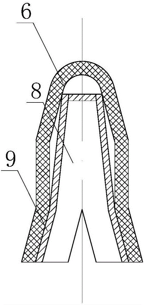
[0042] image 3 Is a cross-sectional view of part 6 of the insulating connecting cap in embodiment 2; Figure 4 Is a three-dimensional schematic diagram of the memory alloy connecting sleeve in embodiment 2; Figure 5 It is a schematic diagram of the shape of the shape memory alloy connecting sleeve deformed after heating. In the figure, the meaning of each reference sign is as follows:

[0043] 8. Base plate; 9. Side wall.

[0044] The difference between this embodiment and embodiment 1 is:

[0045] Preferably, the insulating connection cap 6 is provided with a memory alloy connection sleeve. The memory alloy connection sleeve includes a Y-shaped substrate 8. Both sides of the substrate 8 are provided with side walls 9 respectively. The class wire 4 and the class B wire 5 are adjacent, the height of the side wall 9 is greater than half of the larger diameter of the connected class A wire 4 and the class B wire 5, and the side walls 9 on both sides are at the temperature of the memo...

Embodiment 3

[0049] Image 6 Is a three-dimensional schematic diagram of the memory alloy connecting sleeve in embodiment 3; Figure 7 It is a schematic diagram of the shape of the shape memory alloy connecting sleeve deformed after heating. In the figure, the same reference numerals as those used in the drawings in the foregoing embodiment still use the definition of the reference numerals in the foregoing embodiment, and the new reference numerals in the figures indicate the following meanings:

[0050] 10. Top plate.

[0051] Further preferably, the memory alloy connecting sleeve further includes a top plate 10, and the top plate 10 is connected to a side wall 9 respectively.

[0052] By setting the top plate 10, the upper part of the Class A wire 4 and the Class B wire 5 can be sealed. When the two side walls 9 shrink together, the Class A wire 4 and the Class B wire 5 will not be squeezed out of the memory alloy to connect The sleeve prevents the two wires from being separated and ensures ...


PUM


Abstract

The invention relates to a switch of an electric appliance provided with an electrical heating element and the electric appliance provided with the switch. The switch comprises a switch installing plate, wherein a switch body is installed on the switch installing plate, multiple installing holes for detachably installing the switch installing plate on the outer wall of the electric appliance are formed in the switch installing plate. The switch of the electric appliance provided with the electrical heating element is convenient to mount and dismount, and the switch replacement working amount is decreased. In addition, a flame-retardant box can be also installed on the switch installing plate, the switch body is located between the flame-retardant box and the switch installing plate, and a line via hole is formed in the flame-retardant box. The switch body is protected by arranging the flame-retardant box, the higher temperature inside the switch body and the electric appliance is isolated, accordingly the service life of the switch body is prolonged, and the security coefficient of an electric appliance product is also improved.

Description

Technical field [0001] The invention belongs to the technical field of electric wire connection in electric appliances, and particularly relates to a switch and electric appliance of an electric appliance with an electric heating element. Background technique [0002] Existing stoves, heaters, and household appliances in the world encounter switch failures, and replacement requires a drastic disassembly of the equipment as a whole, wiring from the inside, and replacement of switches, which is more complicated. If the switch circuit is replaced by a non-professional person, if the installation is defective, it will easily lead to accidents such as short circuit and virtual connection in the future. In addition, in the prior art, the side of the switch facing the inside of the appliance is not protected. Once the temperature inside the appliance is too high, the non-metallic components in the switch may be damaged. Summary of the invention [0003] In order to overcome the technica...

Claims


Application Information

Patent Timeline
Patent Type & Authority Applications(China)
IPC IPC(8): H01H9/02H01H9/04
CPCH01H9/0207H01H9/04
Inventor 朱佳音
Owner 朱佳音
Why Eureka
Try Eureka