Sheet metal bending machine

A technology for bending machines and metal sheets, applied in the field of bending machines, can solve problems such as time required, and achieve the effect of quick installation and disassembly

Active Publication Date: 2016-12-14
SALVAGNINI ITAL
View PDF5 Cites 1 Cited by
  • Summary
  • Abstract
  • Description
  • Claims
  • Application Information

AI Technical Summary

Problems solved by technology

However, auxiliary tools must be manually selected, arrange

Method used


Image

  • Sheet metal bending machine
  • Sheet metal bending machine
  • Sheet metal bending machine

Examples


Embodiment Construction

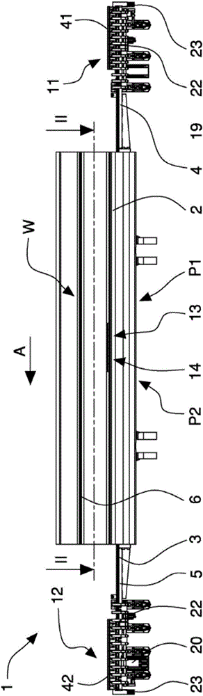
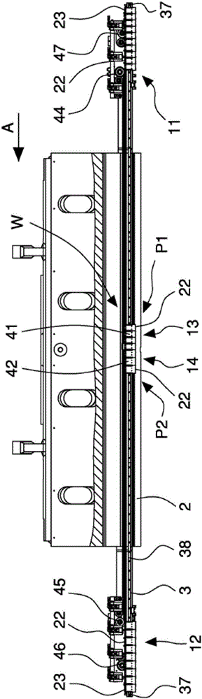
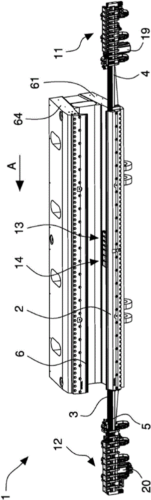
[0035] refer to Figure 1 to Figure 21 A sheet metal bending machine 1 for processing sheet metal components according to the invention comprises a main bending tool member 2 extending along the longitudinal direction A and movable for deforming and bending a workpiece 50 . In the embodiment of the machine shown in the figures, the main bending tool member 2 comprises a bottom or lower linear bending tool which is hinged to the frame 68 of the machine 1 by means of a lower support 61 and is movable about a first axis X1 Rotate so as to contact the workpiece 50 from bottom to top. The axis X1 is horizontal and parallel to the longitudinal direction A. The workpiece 50 is fixed and fastened by the clamping members 62 , 63 . The clamping member comprises an upper clamping member 62 that moves vertically with respect to a fixed lower clamping member 63 forming a support surface B for the workpiece 50 ( Figure 7 ).

[0036] The main bending tool member 2 and clamping members 6...


PUM


Abstract

A sheet metal bending machine comprises main bending tool means (2; 6) that extends along a longitudinal direction (A) and is movable so as to bend a workpiece (50), guide means (3) associated and parallel to the main bending tool means (2; 6), extending through a working zone (W) of the bending machine (1) and sideways protruding from the latter at least with a first end portion (4), and shuttle means (21, 22, 23) slidably mounted on said guide means (3) and supporting at least one auxiliary tool (41, 42) to be associated with the main bending tool means (2; 6) in order to execute partial bends on the workpiece (50); the shuttle means (21, 22, 23) are movable along the longitudinal direction (A) between a first active position (P1), in which the shuttle means (21, 22, 23) is inside the working zone (W) and the auxiliary tool (41, 42) is mounted on the main bending tool means (2; 6), and a first inactive position (R1), in which the shuttle means (21, 22, 23) is outside the working zone (W) and positioned at the first end portion (4) of guide means (3); the shuttle means comprises a first set (11) of shuttles (21, 22, 23), each shuttle (21, 22, 23) carrying a respective auxiliary tool (41, 42), said shuttles (21, 22, 23) being mutually connectable to form a first shuttle convoy (13) having a selectable number of shuttles (21, 22, 23); the first shuttle convoy (13) is movable between said first inactive position (R1) and said first active position (P1) in order to mount a defined composition of auxiliary tools (41, 42) on the main bending tool means (2; 6).

Description

technical field [0001] The invention relates to a bending machine for bending or folding metal strips, segments, plates and sheets for the manufacture of semi-finished and / or finished products. In particular, the invention relates to a bending machine provided with a system for automatically mounting or dismounting auxiliary or additional bending tools adapted to perform partial bending on workpieces. Background technique [0002] Known bending machines or press brakes include mechanical, hydraulic, pneumatic or electrically servo-operated presses that move an upper tool or punch vertically relative to a lower tool or die to deform a workpiece inserted between the tools machine. The upper punch applies a force to the workpiece that deforms and bends the workpiece according to the angle defined by the shape of the tool. The lower die is fixed to the machine frame and includes a longitudinal opening or channel that cooperates with the upper punch to bend the workpiece. [0...

Claims


Application Information

Patent Timeline
IPC IPC(8): B21D5/04B21D37/14B21D5/02
CPCB21D5/0254B21D5/04B21D37/14B21D5/02B21D5/002B21D5/0218
Inventor J·克林埃斯伯杰W·昆泽R·霍克沃纳
Owner SALVAGNINI ITAL
Why Eureka
Try Eureka