Transmission device having a hydraulic system

A technology of hydraulic system and transmission, applied in the direction of transmission, geared components, transmission control, etc., to achieve the effect of reducing hydraulic power consumption

Active Publication Date: 2016-12-14
ZF FRIEDRICHSHAFEN AG
View PDF8 Cites 12 Cited by
  • Summary
  • Abstract
  • Description
  • Claims
  • Application Information

AI Technical Summary

Problems solved by technology

[0005] However, the cooling system of the gear set of the gear transmission designed as a dual-clutch transmission can only be supplied by means of an additional pump which has to be driven by an associated electric motor, so that in the area of ​​the gear set cooling circuit Medium transient undersupply states cannot be compensated with the desired spontaneity by additional pumps

Method used


Image

  • Transmission device having a hydraulic system
  • Transmission device having a hydraulic system
  • Transmission device having a hydraulic system

Examples


Embodiment Construction

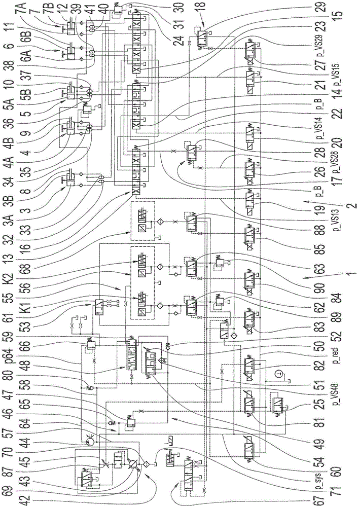
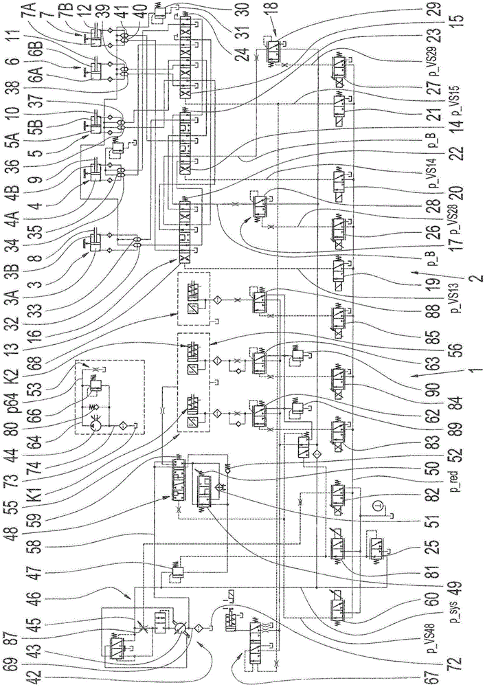
[0048] figure 1 Shows a hydraulic diagram of the transmission device 2 or the hydraulic system 1 of the transmission, or the hydraulic actuation system, currently embodied as a dual clutch transmission, in which nine transmission ratios for forward travel and one transmission ratio for reverse travel can be engaged . These transmission ratios can be switched on and off via five shifting elements 8 - 12 which can be adjusted by hydraulically actuatable piston-cylinder arrangements 3 - 7 . The switching element is presently designed as a switching lever. The actuating pressure p_B can be applied in the area of ​​the piston-cylinder arrangement 3-7 or in the area of ​​the piston chamber 3A, 3B or 4A, 4B or 5A, 5B or 6A, 6B or 7A, 7B via the valve device 16, which valve The device 16 now comprises three pilot-controlled switching valves 13 - 15 coupled to one another via lines. The switching valves 13 - 15 each have a plurality of switching positions for forming the transmissio...


PUM


Abstract

A hydraulic system (1) of a transmission device (2) is connected to a hydraulic pump (43) which can be driven via a transmission input shaft and to a further hydraulic pump (44) which can be driven via a transmission shaft, and conducts hydraulic fluid volumes, which are delivered by the hydraulic pumps (43, 44), to transmission components. Hydraulic fluid can be applied to transmission components via a primary pressure circuit (46) and via a secondary pressure circuit (54). A pressure side (45) of the hydraulic pump (43) is coupled directly to the primary pressure circuit (46) and can be connected to the secondary pressure circuit (54) via the system pressure valve (47). A pressure side (64) of the further hydraulic pump (44) is connected directly to the secondary pressure circuit (54). The pressure side (45) of the hydraulic pump (44) can be connected in the region of the secondary pressure circuit (54) via a valve device (48) to a transmission component configured as a wheelset and to a transmission component configured as a dual clutch system (56) and also to an intake region (69) of the hydraulic pumps (43, 44). The pressure side (64) of the further hydraulic pump (44) is connected to the wheelset and can be coupled to the dual clutch system (56) via the valve device (48).

Description

technical field [0001] The invention relates to a transmission arrangement with a hydraulic system of the type defined in more detail in the preamble of claim 1 . Background technique [0002] A hydraulic distribution system for a transmission is known from DE 10 2011 077 552 A1, by means of which a supply of hydraulic medium to components of a vehicle transmission can be carried out. The hydraulic arrangement comprises at least one main pump device driven on the drive side for supplying the primary hydraulic circuit with primary pressure, and the hydraulic arrangement is additionally formed with at least one auxiliary pump which can be driven on the output side, the additional pump Used to supply secondary pressure to the secondary hydraulic circuit. The additional pump device is connected directly to the primary hydraulic circuit or directly to the secondary hydraulic circuit, wherein the coupling device is provided for coupling the additional pump device to the output pa...

Claims


Application Information

Patent Timeline
Patent Type & Authority Applications(China)
IPC IPC(8): F16H61/688F16H61/00
CPCF16H57/0435F16H57/0446F16H61/0025F16H61/2807F16H61/688F16H2061/0037F16H3/006F16H57/0441F16H61/0206
Inventor R·诺瓦克T·普夫勒格
Owner ZF FRIEDRICHSHAFEN AG
Why Eureka
Try Eureka