
Pressure relief device and pressure relief system for emulsion pump station

A technology of emulsion pumping station and pressure relief device, which is applied to the parts, pump control, pump components and other directions of the pumping device used for elastic fluid, so as to achieve the effect of convenient installation and disassembly, and reduce hydraulic power consumption

Pending Publication Date: 2021-06-18
BEIJING HUAHAI MACHINERY
View PDF0 Cites 0 Cited by
  • Summary
  • Abstract
  • Description
  • Claims
  • Application Information

AI Technical Summary

Problems solved by technology

[0004] In view of the above-mentioned related technologies, the inventor believes that: in the unloaded state, since the emulsion pump is still running and continues to supply liquid to the outside, when the liquid discharge volume of the pressure relief device is less than the liquid supply volume of the pump, the pump and the liquid supply A hydraulic pressure value will still be maintained in the system, the pump is not in a zero-load operation state, and still has a certain hydraulic power consumption

Method used


Image

  • Pressure relief device and pressure relief system for emulsion pump station
  • Pressure relief device and pressure relief system for emulsion pump station
  • Pressure relief device and pressure relief system for emulsion pump station

Examples


Embodiment Construction

[0037] The following is attached Figure 1-4 The application is described in further detail.

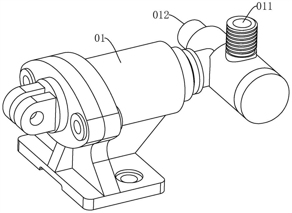
[0038] refer to figure 1 , the plunger pump includes a plunger pump body 0, one side of the plunger pump body 0 is provided with a liquid suction port 011, and the other side of the plunger pump is provided with a liquid discharge port 012, and inside the plunger pump body 0 is a liquid suction port 011 A liquid suction valve (not shown in the figure) is provided at , and a liquid discharge valve (not shown in the figure) is provided at the discharge port 012 inside the plunger pump body 0 .

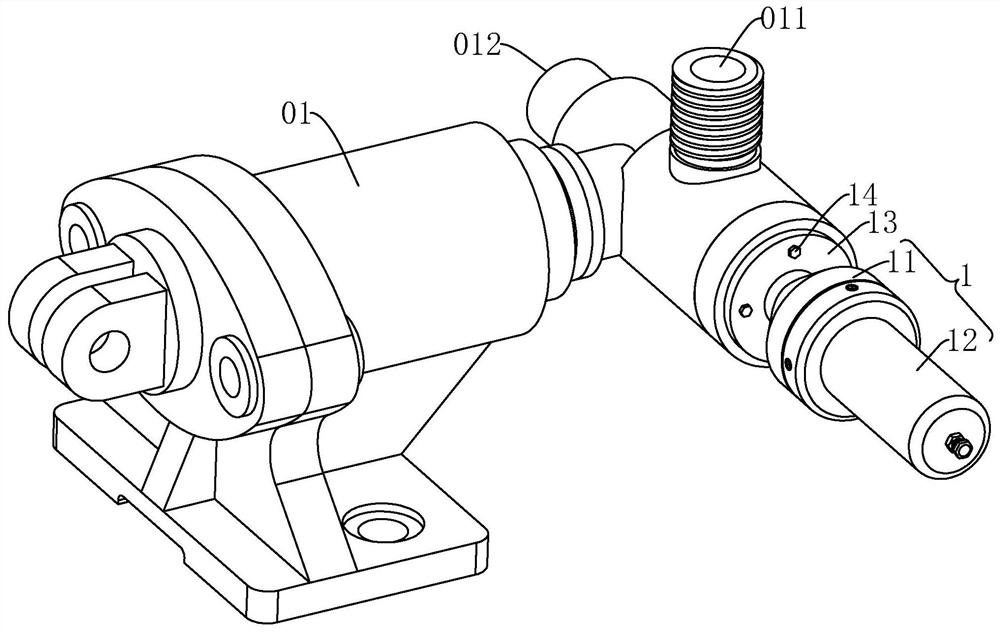
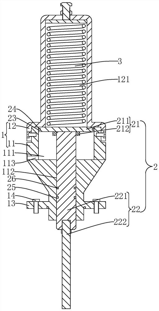
[0039] The embodiment of the application discloses a pressure relief device for an emulsion pumping station. refer to figure 2 and image 3 , the pressure relief device includes a mounting seat 1 installed at one end of the plunger pump suction valve and a pressure relief rod 2 slidingly connected inside the mounting seat 1, wherein one end of the pressure relief rod 2 protrudes from the m...


PUM


Abstract

The invention relates to a pressure relief device and a pressure relief system for an emulsion pump station, and relates to the field of hydraulic pipeline pressure relief. The pressure relief device comprises a mounting seat mounted at one end, close to a liquid suction valve, of a plunger pump and a pressure relief rod slidably connected in the mounting seat, one end of the pressure relief rod extends out of the mounting seat. When the pressure relief rod slides in the mounting seat, a valve element of the liquid suction valve on the plunger pump can be ejected open to achieve pressure relief. The pressure relief device and the pressure relief system for the emulsion pump station have the effects that an emulsion pump can run in a zero-load mode in the pressure relief state, and hydraulic power consumption is reduced.

Description

technical field [0001] The present application relates to the field of hydraulic pipeline pressure relief, in particular to a pressure relief device and a pressure relief system for an emulsion pumping station. Background technique [0002] Emulsion pumping station is a kind of equipment installed underground in coal mines to provide hydraulic power source for hydraulic equipment. It consists of two parts: emulsion pump and liquid tank. The emulsion pump is a plunger pump. When the hydraulic equipment is out of service or the amount of liquid is reduced, the hydraulic pressure in the liquid supply system will increase. When it rises above the set value, it will affect the normal operation of the hydraulic equipment. Therefore, it is necessary to drain the hydraulic system in time. pressure. [0003] The plunger pump drives the slider to make a reciprocating linear motion through the crank connecting rod, and uses the pressure change in the cylinder to make the suction valve...

Claims


Application Information

Patent Timeline
Patent Type & Authority Applications(China)
IPC IPC(8): F04B49/22F04B53/04F04B53/10F04B53/22
CPCF04B49/22F04B53/04F04B53/10F04B53/22
Inventor 杜建华何珊杨淑芳褚峰伟
Owner BEIJING HUAHAI MACHINERY
Learn More