Pedicle Screw and Device for Injecting Bone Cement into Bone

a technology of bone cement and pedicle screw, which is applied in the field of pedicle screw and device for injecting bone cement into bone, can solve the problems of insufficient calcium and collagen content in bone, weak fixing force of rod b>3/b>, and insufficient structure adaptability for practical use, so as to facilitate and stably implant bone, improve fixing force, and be used stably for osteoporosis

Inactive Publication Date: 2007-12-27
HER JI HOON +1
View PDF17 Cites 91 Cited by
  • Summary
  • Abstract
  • Description
  • Claims
  • Application Information

AI Technical Summary

Benefits of technology

[0009] Therefore, the present invention has been made in view of the above-mentioned problems, and it is an object of the present invention to provide a pedicle screw which can be easily and stably implanted into bone at a time by means of a coupling section including a rod support section integrally formed with a fixing bolt capable of enhancing fixing force with respect to a rod, and which can be stably used for osteoporosis patients by injecting bone cement into bones of osteoporosis patients through a hollow section formed in a screw rod of the pedicle screw.
[0010] Another object of the present invention is to provide a device for easily injecting bone cement having relatively high density into bone around a pedicle screw implanted into the bone.

Problems solved by technology

However, the conventional pedicle screw 2 having the above structure presents a problem in that fixing force for the rod 3 is weak because the rod 3 is simply fixed by the fixing bolt 6.
However, such a structure is not adaptable for practical use because it is difficult to place the plate between the rod 3 and the fixing bolt 6 in a state that the rod 3 is accommodated in the head section 5 of the screw rod 4.
However, in cases of osteoporosis patients, an amount of calcium and collagen contained in bone may be insufficient, so a plurality of pores are formed in the bone and the bone becomes thin.
For this reason, the bone may be easily broken even if relatively weak impact is applied to the bone.
However, when the pedicle screw 2 is implanted into the spine 1 after injecting the bone cement into the spine 1, it is difficult to implant the pedicle screw 2 into the spine 1 due to increased strength of the spine 1.
In addition, when the bone cement is injected into the spine 1 after the pedicle screw 2 has been implanted into the spine 1, it is difficult to inject the bone cement into the spine 1 around the pedicle screw 2.

Method used


Image

  • Pedicle Screw and Device for Injecting Bone Cement into Bone
  • Pedicle Screw and Device for Injecting Bone Cement into Bone
  • Pedicle Screw and Device for Injecting Bone Cement into Bone

Examples


Embodiment Construction

[0023] Reference will now be made in detail to the preferred embodiments of the present invention.

[0024] Hereinafter, a preferred embodiment of the present invention will be described with reference to accompanying drawings.

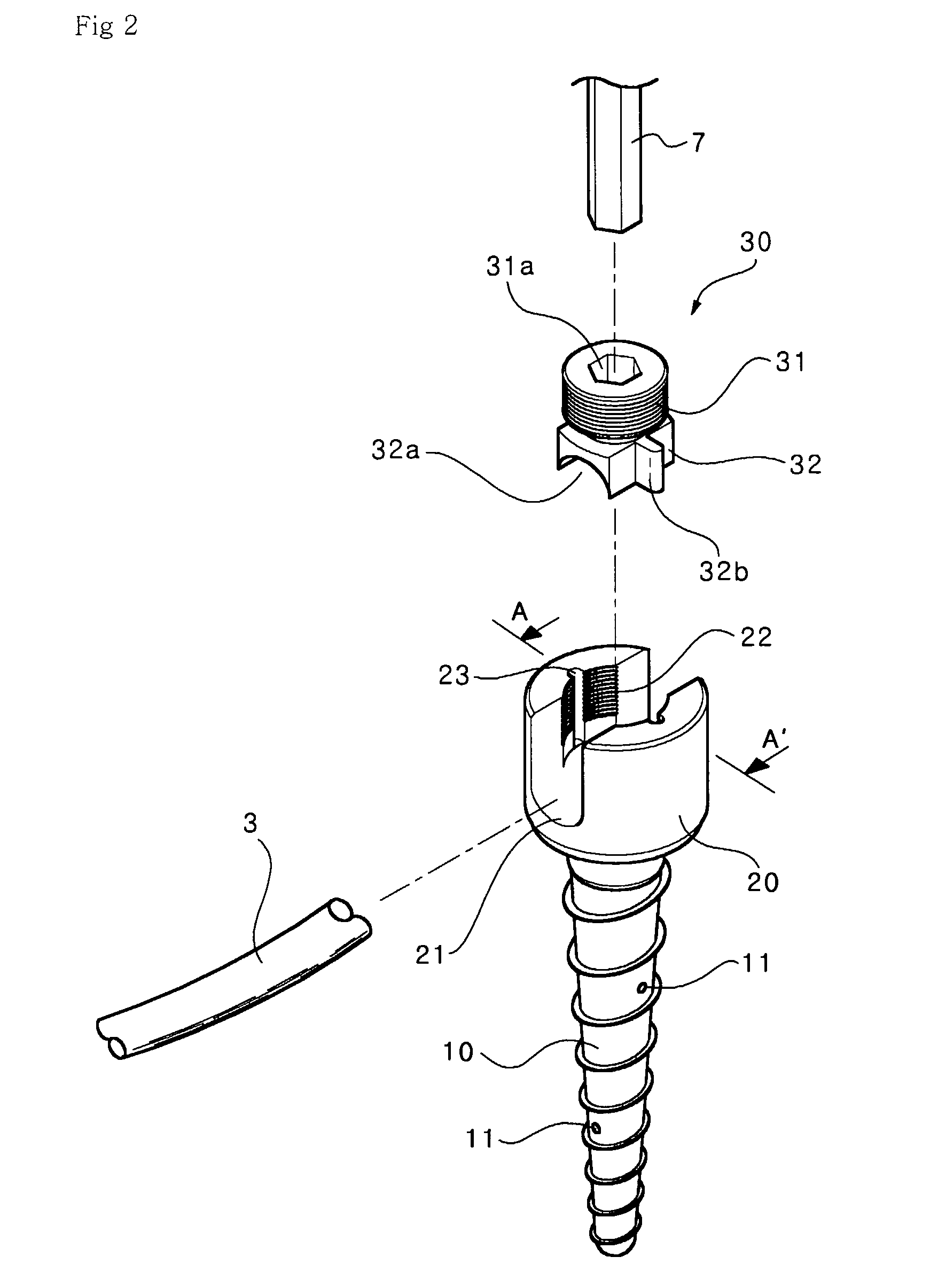
[0025]FIG. 2 is an exploded perspective view illustrating a pedicle screw according to one embodiment of the present invention.

[0026] As shown in FIG. 2, pedicle screw includes a screw rod 10, which is directly inserted into a spine. The screw rod 10 is formed at an outer surface thereof with a screw section. Injection holes 11 are formed in the screw rod 10 so as to inject bone cement into the spine.

[0027] The screw rod 10 is provided at an upper portion thereof with a head section 20, which is formed at an inner portion thereof with a U-shaped recess 21. When the pedicle screw is implanted into the spine, a rod 3 is rested in the U-shaped recess 21. The U-shaped recess 21 is formed with a feeding hole 12 for feeding bone cement. A screw part 22 is formed at...


PUM


Abstract

Disclosed is a pedicle screw used in spinal fusion surgery and a device for injecting bone cement into a spine having low bone mineral density by using the pedicle screw so as to enhance strength of the spine. The pedicle screw includes a screw rod fixedly inserted into a bone, a head section provided at an upper portion of the screw rod and formed at an inner portion thereof with a U-shaped recess and a screw part, and a coupling section coupled with the screw part of the head section. The coupling section is coupled with a rod support section including a bolt having a screw structure provided at an upper portion of the rod support section, a reverse U-shaped recess formed at a lower portion of the rod support section, and a pair of protrusions provided at lateral portions of the rod support section. The screw part of the head section is formed with a pair of guide slots. The screw rod is formed at an inner portion thereof with a hollow section, injection holes communicated with the hollow section are formed in the screw rod, and a feeding hole is formed in the U-shaped recess for feeding bone cement. The bone cement injection device has a cannula including an elongated body, a pedicle screw coupling member provided at one end of the elongated body so as to be fixed to the pedicle screw, and a handle provided at the other end of the elongated body and having an injector coupling member which is coupled to an inlet of an injector, and an impactor including an elongated cylindrical pressing rod inserted into the elongated body of the cannula and having a length longer than a length of the elongated body of the cannula, and a handle attached to one end of the elongated cylindrical pressing rod.

Description

TECHNICAL FIELD [0001] The present invention relates to a pedicle screw used in spinal fusion surgery and a device for injecting bone cement into a spine having low bone mineral density by using the pedicle screw so as to enhance strength of the spine. BACKGROUND ART [0002] In general, spinal cord injured patients who may hardly stand erect must undergo a surgical operation in order to implant an artificial aid into an injured spine for supporting the injured spine. Such an artificial aid for supporting the injured spine includes a pedicle screw installed at upper and lower portions of the injured spine for fixing the injured spine and a rod connected to the pedicle screw so as to support the injured spine. [0003]FIG. 1 is a view illustrating a conventional pedicle screw implanted into a spine. As shown in FIG. 1, when a pedicle screw 2 and a rod 3 are implanted into the spine 1, a screw rod 4 of the pedicle screw 2 is inserted into the spine 1 in vertical to the spine 1 and the rod...

Claims


Application Information

Patent Timeline
Patent Type & Authority Applications(United States)
IPC IPC(8): A61B17/58A61B17/56
CPCA61B17/7032A61B17/7098A61B17/8827A61B17/8816A61B17/8822A61B17/864
Inventor HER, JI-HOONKIM, SANG-HYOUNG
Owner HER JI HOON
Why Eureka
Try Eureka