
Distributed fault injection mechanism

a fault injection and distribution technology, applied in error detection/correction, instruments, computing, etc., can solve the problems of automatic computing systems, application must be explicitly instrumented with state notifications, and both tools lack a broader fault model and the ability to define precise triggers. to achieve the effect of facilitating error injection

Inactive Publication Date: 2008-09-04
IBM CORP
View PDF7 Cites 87 Cited by
  • Summary
  • Abstract
  • Description
  • Claims
  • Application Information

AI Technical Summary

Benefits of technology

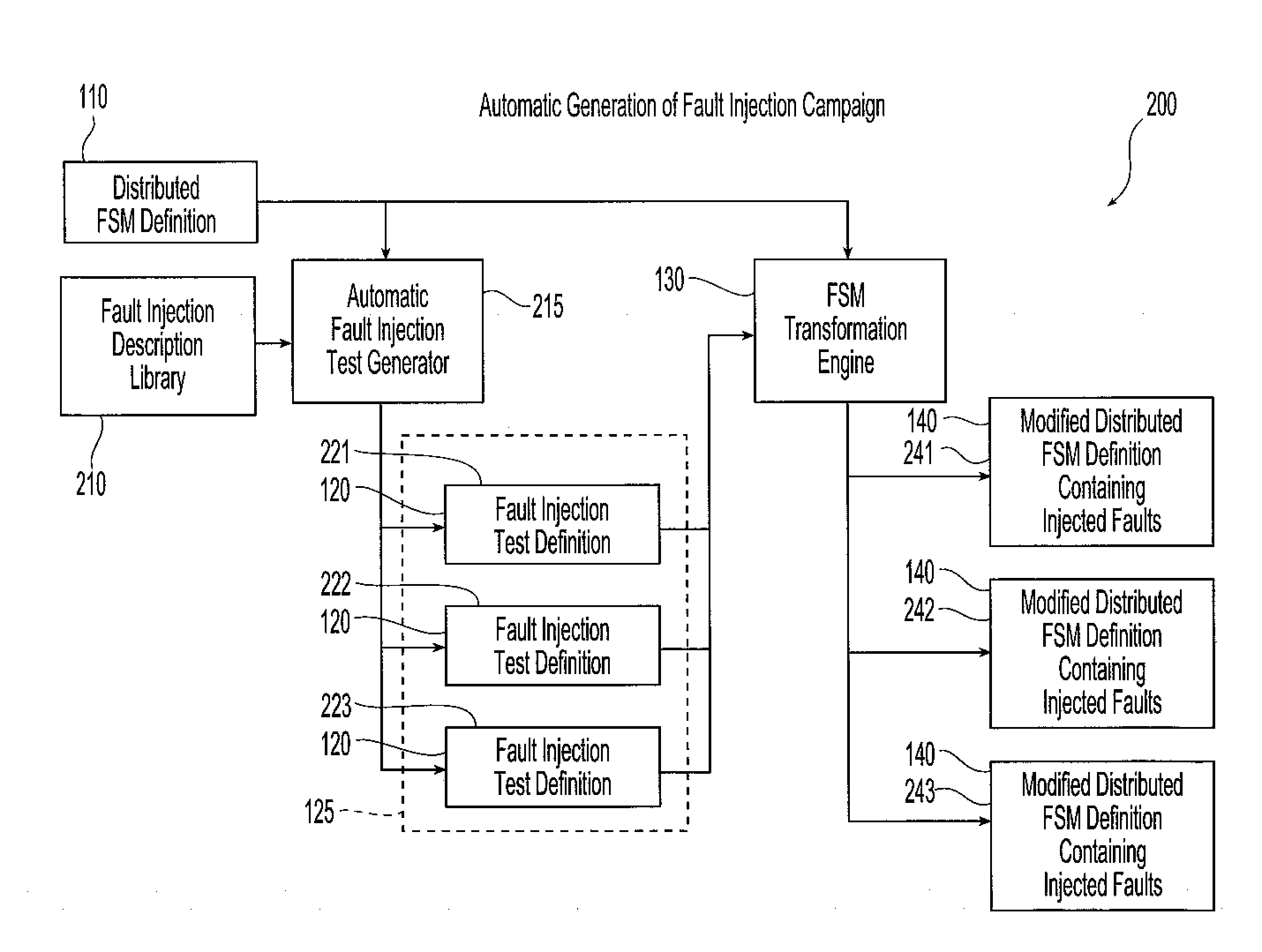
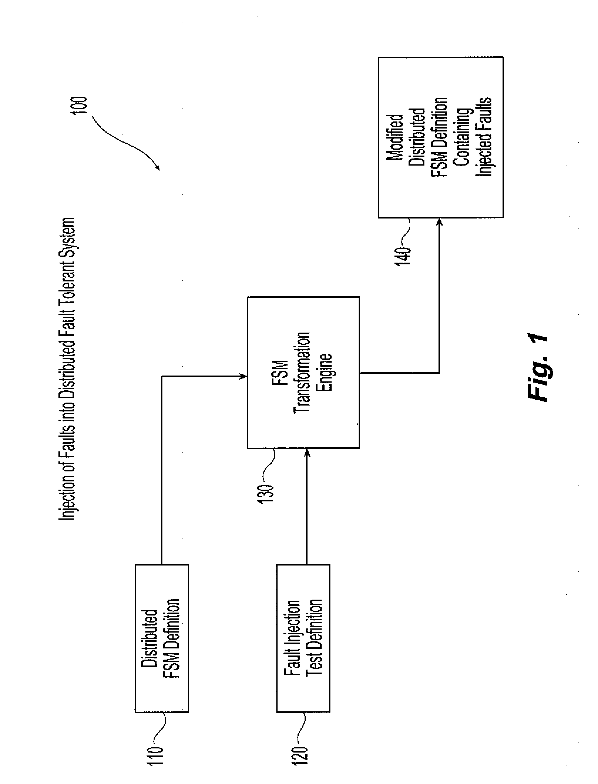
[0007]Systems and methods in accordance with the present invention provide for validating the robustness of a distributed computing system driven by a finite state machine (FSM) by augmenting the state machine definition to permit a test engineer to inject errors based on the system state and to facilitate injection of errors in other nodes of the distributed computing system. The distributed computing system can then be precisely tested under an array of fault conditions. Providing fault injection in a plurality of different system states guarantees that the system is tested in different scenarios, increasing the number of test cases and the test coverage of the fault tolerance mechanisms.
[0008]In accordance with exemplary embodiments of the present invention, a FSM description is automatically modified in a controlled manner to define fault injection tests without modifying the control flows originally defined by the FSM. Precise fault injection triggers are defined based on the application state, allowing the test engineer to increase the test coverage.

Problems solved by technology

The ability of autonomic computing systems to survive under various abnormal behaviors of all the participating components distributed across a network of nodes remains a challenge.
Both tools lack a broader fault model and the ability to define precise triggers based on application state.
The drawback of this approach is that the application has to be explicitly instrumented with state notifications and fault injection code.
Such tasks get more complicated when the system runs in a heterogeneous environment, where there is no guarantee concerning the language in which the applications are implemented and the state in which each of these pieces will be disposed in at each time interval.
Multithreaded applications where each thread has its own state may also cause problems when defining a state for a single process.

Method used


Image

  • Distributed fault injection mechanism
  • Distributed fault injection mechanism
  • Distributed fault injection mechanism

Examples


Embodiment Construction

[0028]Systems and methods in accordance with the present invention provide for the verification and validation of detection and recovery mechanisms within fault tolerant autonomic computing systems. Reliability in the detection and recovery mechanisms is provided by testing the detection and recovery mechanism under a variety of fault scenarios. In one embodiment, the distributed application or distributed computing system is described using a finite state machine (FSM). Suitable methods for using FSM's to describe and to materialize a distributed application are disclosed in U.S. patent application Ser. No. 11 / 444,129, filed May 31, 2006 and titled “Data Driven Finite State Machine For Flow Control”. Exemplary systems for fault emulation in accordance with the present invention also include a fault injection library or plug-in, which implements the behavior of the faults to be injected, and a fault injection campaign language to describe the test experiment. A FSM transformation en...


PUM


Abstract

Methods and systems are provided for testing distributed computer applications using finite state machines. A finite state machine definition for use in a distributed computer system is combined with the fault injections definitions contained within a fault injection campaign that is created for testing the computer application employing that finite state machine. The definition and combination of the finite state machine definition and the fault injection campaign is carried out automatically or manually, for example using a graphical user interface. This combination creates at least one modified finite state machine definition containing the desired injected faults. The modified finite state machine definition is separate from the originally identified finite state machine definition, and the originally identified finite state machine remains intact without injected faults. Trigger points within the finite state machine definition are identified for each fault injection test definition, and the modified finite state machine definition containing the fault injection test definition associated with a given trigger point are used in place of the original finite state machine definition upon detection of that trigger point during runtime of the finite state machine definition.

Description

STATEMENT REGARDING FEDERALLY SPONSORED RESEARCH[0001]The invention disclosed herein was made with U.S. Government support under Contract No. H98230-05-3-0001 awarded by the U.S. Department of Defense. The Government has certain rights in this invention.FIELD OF THE INVENTION[0002]The present invention relates to validation and testing of dependable systems.BACKGROUND OF THE INVENTION[0003]In autonomic computing systems, self-healing and self-management are key characteristics. To reach high availability requirements, these autonomic computing systems have to minimize recovery time and assure that they can react and diagnose faults correctly. The ability of autonomic computing systems to survive under various abnormal behaviors of all the participating components distributed across a network of nodes remains a challenge. Tools have been developed to conduct tests that emulate these abnormal behaviors to verify that a given autonomic computing system will function as expected in resp...

Claims


Application Information

Patent Timeline
Patent Type & Authority Applications(United States)
IPC IPC(8): G06F11/00
CPCG06F11/263
Inventor DEGENARO, LOUIS R.CHALLENGER, JAMES R.GILES, JAMES R.JACQUES DA SILVA, GABRIELA
Owner IBM CORP
Learn More