Fluid transportation device

Inactive Publication Date: 2007-07-05
SEIKO EPSON CORP +1
View PDF4 Cites 93 Cited by
  • Summary
  • Abstract
  • Description
  • Claims
  • Application Information

AI Technical Summary

Benefits of technology

[0198] With above arrangement, by the outer case being formed to have the protruding surface or the recessed surface or both the protruding surface and the recessed surface as described above, the outer case is formed to have the skin side surface shape or the rear surface shape that becomes substantially aligned with the subcutaneous shape of the animal, etc., even in the narrow width direction when the fluid transpor

Problems solved by technology

However, with a structure that enables such operation, it is difficult to ensure waterproofness between the pump module and the motor module, and thus implantation inside a living body is not satisfactory.
In assembling by engaging the pinion and the gear in this manner, because the pinion and the gear are normally not matched in phase, the workability is significantly poor.
It is also predicted that the pinion and the gear become flawed easily, and this may obstruct driving in the case of low torque driving using a step motor for a watch.
Furthermore, to perform driving upon addition of the drug solution, the reservoir must be exchanged, and this may cause interruption of continuous injection of the drug solution.
H5-74511, because a drug solution feeding unit is disposed at the exterior of the experimental animal, the drug solution feeding unit tends to move away from the experimental animal when the experimental animal moves around and there is thus the danger that the catheter will become removed from the experimental animal.
Also, because the catheter is inserted into the experimental animal, there is a high possibility of

Method used


Image

  • Fluid transportation device
  • Fluid transportation device
  • Fluid transportation device

Examples


first embodiment

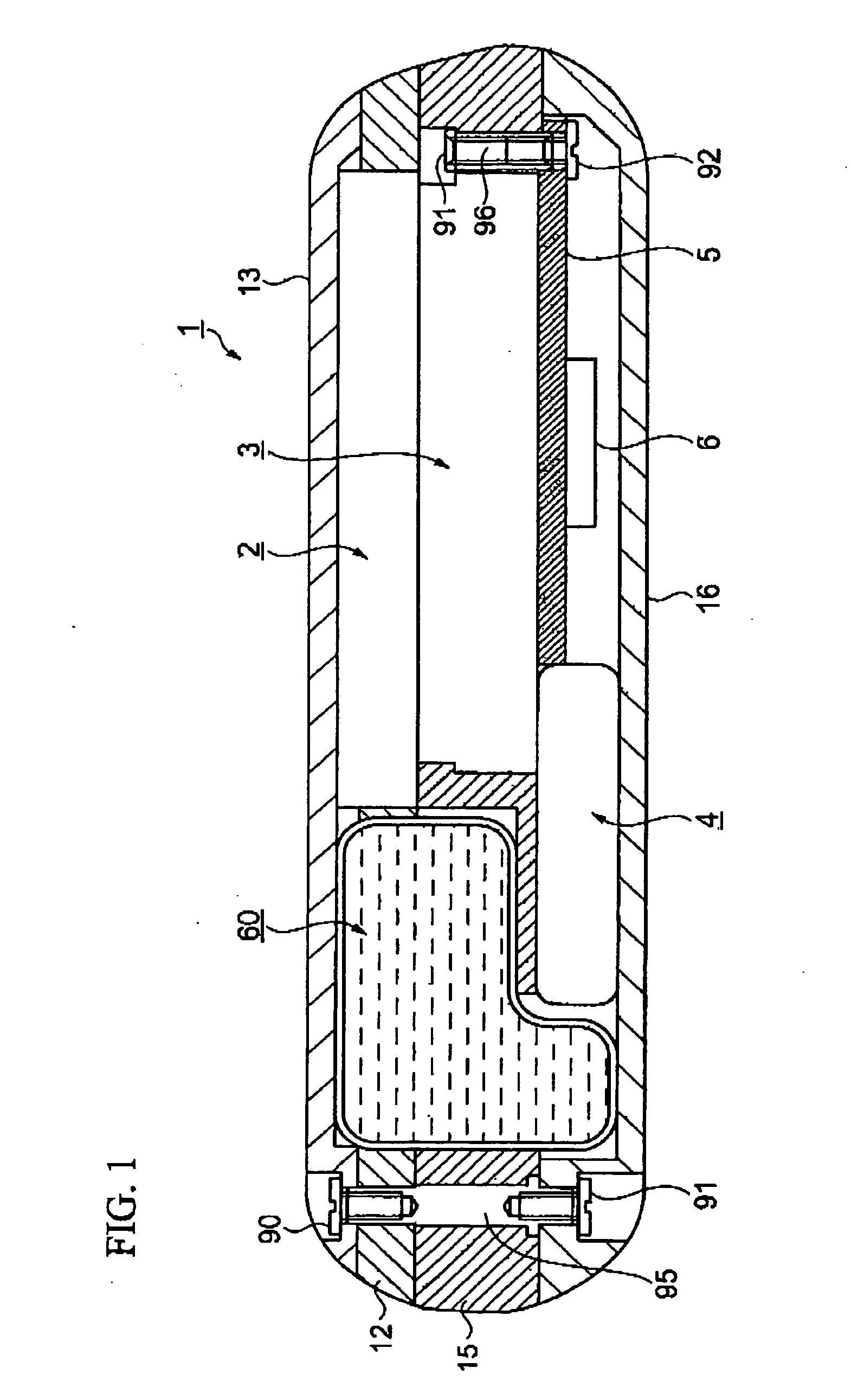
[0237] FIGS. 1 to 6 show a fluid transportation device according to a first embodiment of this invention.

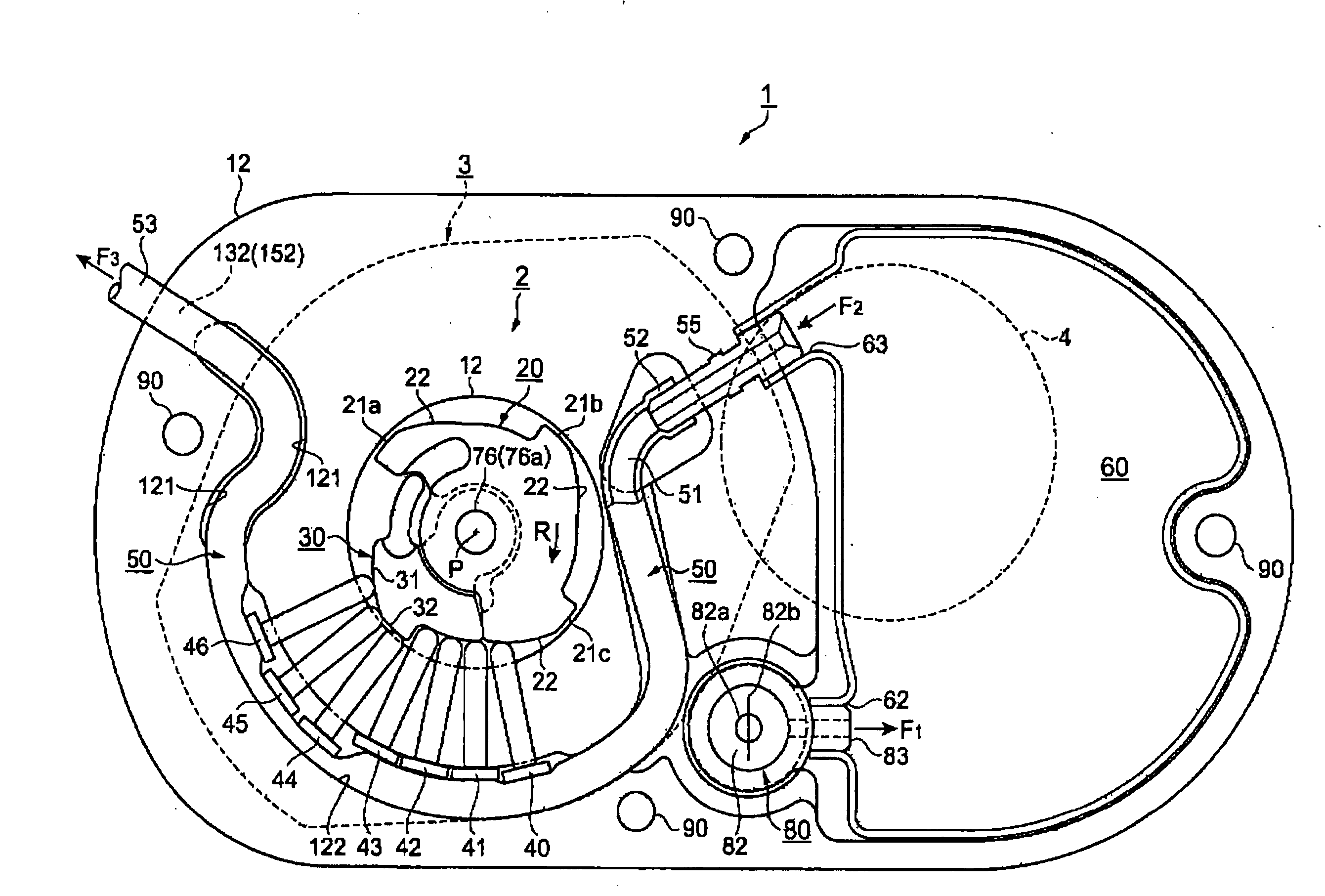
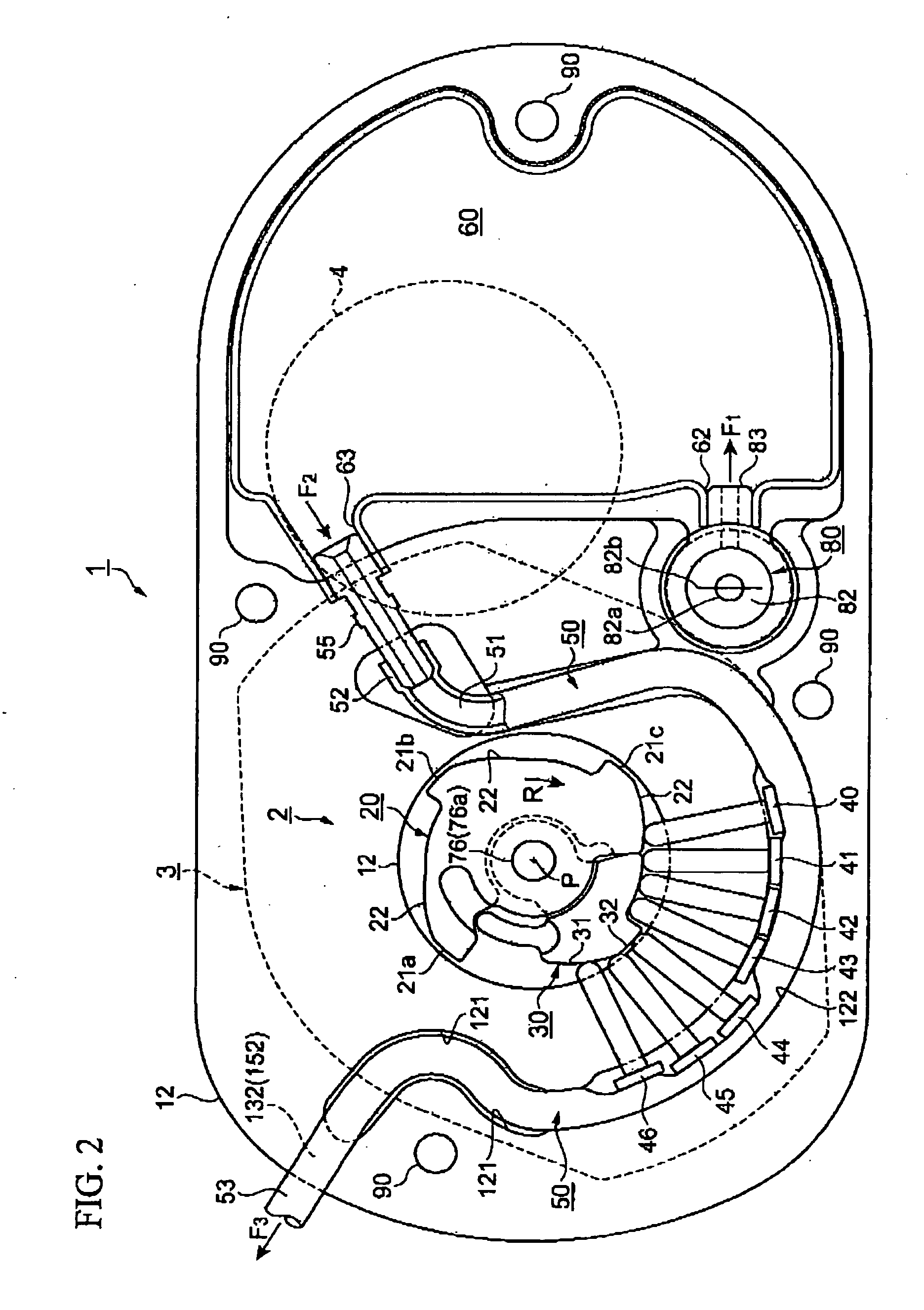
[0238]FIG. 1 shows an arrangement in a thickness direction, FIG. 2 shows the arrangement in a plan view direction, FIG. 3 is a plan view of a watch movement that is employed as a driving force transmission mechanism, FIG. 4 is a cross-sectional view of portions of the driving force transmission mechanism and a fluid transport mechanism, FIG. 5 is a cross-sectional view of a structure related to injection and outflow of a fluid, and FIG. 6 is a plan view of the fluid transport mechanism.

[0239] With the present embodiment, a fluid transportation device that is implanted in a living body of a human being, animal, etc., and uses a drug solution as a fluid shall be described as an example.

[0240] Gel-like fluids and gases are included in the definition of “fluid.”

[0241]FIGS. 1 and 2 are respectively a cross-sectional view and a plan view of the basic arrangement of a fluid transport...

second embodiment

[0389] FIGS. 7 to 9 show a fluid transportation device according to a second embodiment of this invention.

[0390]FIG. 7 shows an arrangement in a planar direction.

[0391]FIGS. 8A and 8B are diagrams of arrangements in a thickness direction, with FIG. 8A being a diagram as viewed from a narrow width side and FIG. 8B being a diagram as viewed from a wide width side.

[0392]FIGS. 9A to 9C are diagrams of a reservoir frame, with FIG. 9A being a plan view, FIG. 9B being a front view, and FIG. 9C being a side view.

[0393] The present embodiment is the same as the first embodiment in that a fluid transportation device, which is implanted in a living body of a human being, animal, etc., and uses a drug solution as a fluid, is described as an example, although gel-like fluids as well as gases are also included in the meaning of “fluid.”

[0394] The main points of difference of a fluid transportation device 160 according to the second embodiment shown in FIGS. 7 and 8 with respect to the fluid t...

third embodiment

[0454] As the third embodiment of this invention, a drug solution feeder (fluid transportation device) for implantation under the skin of an experimental animal shall be described.

[0455] Here, a drug solution is used as the fluid, and the implantation subject is an experimental animal.

[0456]“Experimental animal” refers to a small animal, such as a mouse, rat, guinea pig, etc., on which an animal experiment concerning the drug solution can be performed.

[0457]“Drug solution” refers, for example, to a medical liquid or nutrient liquid or to any liquid for performing an animal experiment for development of such liquids or performing a medical treatment on an animal.

[0458]FIGS. 10A to 10D are external views of the drug solution feeder for implantation under the skin of an experimental animal.

[0459]FIG. 10A is a lower side view as viewed from a lower side of the drug solution feeder and is a side view as viewed from the nearer side of the paper surface of FIG. 12, FIG. 10B is an uppe...


PUM


Abstract

A fluid transportation device includes: an outer case having a sealed space; a tube having elasticity; a fluid transport mechanism having fingers that occlude the tube and a cam that successively presses the plurality of fingers; a driving force transmission mechanism disposed so as to be overlapped with the fluid transport mechanism, and transmitting a driving force to the fluid transport mechanism; a reservoir disposed at a position so as not to overlap the fluid transport mechanism and the driving force transmission mechanism; a port through which the fluid is injected into the reservoir; and an electric power supply supplying electric power to the driving force transmission mechanism. In this fluid transportation device, at least the fluid transport mechanism, the driving force transmission mechanism, and the electric power supply are housed in the sealed space of the outer case.

Description

CROSS-REFERENCE TO RELATED APPLICATION [0001] This application claims priority from Japanese Patent Application No. 2005-332450, filed on Nov. 17, 2005, Japanese Patent Application No. 2006-030580, filed on Feb. 8, 2006, Japanese Patent Application No. 2006-070685, filed on Mar. 15, 2006, and Japanese Patent Application No. 2006-304456, filed on Nov. 9, 2006, the contents of which are incorporated herein by reference. BACKGROUND [0002] 1. Technical Field [0003] The present invention relates to a fluid transportation device, in which a tube is pressed to make a fluid flow. [0004] Specifically, this invention relates to a structure of a fluid transportation device, in which a driving force transmission mechanism for watch movement is used as a fluid transport mechanism, the fluid transport mechanism and the driving force transmission mechanism are overlapped, these mechanisms and a reservoir are positioned in a planarly shifted configuration, and the mechanisms are sealingly housed in...

Claims


Application Information

Patent Timeline
IPC IPC(8): F04B43/08
CPCA61M5/14228A61M5/14232A61M5/1424A61M2005/14506A61M39/0208F04B23/025F04B43/082A61M5/14276
Inventor MIYAZAKI, HAJIMEMIYASAKA, MAMORUKAWASUMI, KAZUOMOCHIZUKI, EIJIKOBAYASHI, SUSUMUMORI, TOSHIOHASHIMOTO, NAO
Owner SEIKO EPSON CORP
Why Eureka
Try Eureka