
Valve plate manufacturing method

A valve plate and plate body technology, applied in the field of valve plate manufacturing methods, can solve the problems of inability to block fluids, cost money, and cannot be used in high temperature environments, and achieve the effect of simplifying the cutting operation process and improving production efficiency

Inactive Publication Date: 2016-12-21
刘千于
View PDF7 Cites 0 Cited by
  • Summary
  • Abstract
  • Description
  • Claims
  • Application Information

AI Technical Summary

Problems solved by technology

[0004] It can be seen from the above that the valve plate manufactured by the traditional valve plate manufacturing method can only touch the conveying pipe on the same plane. Once the size is slightly unable to match the radial size of the conveying pipe, it cannot block the fluid, so it needs to be matched. plastic material
However, plastic (or rubber) materials cannot be used in high-temperature environments, and will deteriorate after a period of use, and need to be replaced regularly, which is not only labor-intensive and time-consuming, but also expensive. Therefore, the known manufacturing method of the valve plate needs to be improved urgently. disadvantages

Method used


Image

  • Valve plate manufacturing method
  • Valve plate manufacturing method
  • Valve plate manufacturing method

Examples


Embodiment Construction

[0032] The following examples illustrate possible implementations of the present invention, but are not intended to limit the protection scope of the present invention.

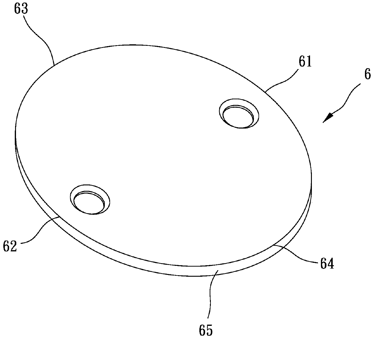
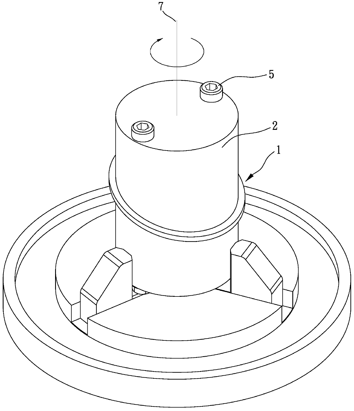
[0033] Please refer to Figure 1 to Figure 9 , which shows a preferred embodiment of the present invention, the valve plate manufacturing method of the present invention comprises the following steps:

[0034] At least one piece 1 is provided, and each piece 1 has a first side 11 and a second side 12 opposite to each other in the thickness direction. The at least one piece 1 is fixed on a jig 2 . A cutting edge 31 having a transverse direction to the first side 11 of the at least one piece 1 is provided. Make the cutting edge 31 cut the at least one piece of body 1 along a closed cutting path (not shown in the figure) relative to the at least one piece of body 1. An end point 61 and a second end point 62 , and a third end point 63 and a fourth end point 64 opposite to each other. Wherein, the cutting edge...


PUM


Abstract

The invention relates to a valve plate manufacturing method. The valve plate manufacturing method comprises the following steps of providing at least one plate body, wherein each plate body is provided with a first side face and a second side face which are opposite to each other in the thickness direction; fixing the at least one plate body to a jig; providing a cutting edge which is arranged crosswise relative to the first side face of the at least one plate body; and enabling the cutting edge to cut the at least one plate body along a closed cutting path relative to the at least one plate body, wherein the closed cutting path includes a first end point, a second end point, a third end point and a fourth end point, the first end point and the second end point are opposite to each other in one direction of the at least one plate body, the third end point and the fourth end point are opposite to each other in another direction, perpendicular to the direction with the first end point and the second end point, of the at least one plate body, each plate body is cut by the cutting edge along the closed cutting path to form a first circumferential surface and a second circumferential surface, the first circumferential surface and the second circumferential surface are located on the two sides of the connecting line between the first end point and the second end point respectively, the first circumferential surface inclines towards the first side face, and the second circumferential surface inclines towards the second side face.

Description

technical field [0001] The invention relates to the technical field of valve plate manufacturing, in particular to a valve plate manufacturing method. Background technique [0002] Generally, there are devices that use fluid, and a valve mechanism is usually set in the delivery pipeline to control the flow of fluid. Wherein, the valve mechanism is provided with a valve plate in the delivery pipeline, through which the flow of the fluid is partially / completely blocked to achieve the purpose of controlling the flow. [0003] The traditional manufacturing method of the valve plate is to cut according to the radial size of the conveying pipe. The circumferential surface of the valve plate is in the same direction and parallel to the outer contour of the conveying pipe. Usually, a plastic (or rubber) gasket is installed on the valve plate. And between the inner wall of the delivery pipeline to ensure that the valve plate can be tightly sealed with the inner wall of the delivery ...

Claims


Application Information

Patent Timeline
IPC IPC(8): B23Q15/007F16K51/00
Inventor 刘千于
Owner 刘千于
Learn More