Plate pressing forming mold with cutting knife
A technology of pressing and cutting knives, applied in the direction of molds, forming indenters, ceramic molding machines, etc., can solve the problem of not having cutting knives, and achieve the effect of reducing processing procedures, saving physical strength, and simplifying the cutting process.
- Summary
- Abstract
- Description
- Claims
- Application Information
AI Technical Summary
Problems solved by technology
Method used
Image
Examples
Embodiment 1
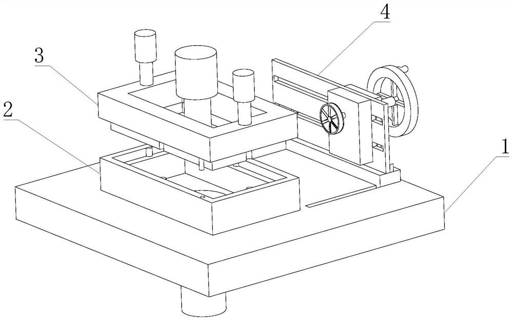
[0034] Such as Figure 1-7 As shown, the present invention provides a plate press molding mold with a cutting knife, including a chassis 1, a lower mold 2 is fixedly installed on the left end of the upper surface of the chassis 1, an upper mold 3 is movably installed above the lower mold 2, and an upper mold 3 is installed on the upper surface of the chassis 1. The right end movable cutting device 4 is installed.
[0035] In this embodiment, the upper mold 3 cooperates with the lower mold 2 to press-form the plate, and after the press-form and demoulding, the edge of the plate will be cut by the mobile cutting device 4 .
[0036] Such as Figure 1-7 As shown, in this embodiment, preferably, the mobile cutting device 4 includes a mounting plate 42, the rear surface of the mounting plate 42 is movably mounted with a moving device box 44, and the front surface of the mounting plate 42 is movably mounted with a cutting device box 45, The rear surface of the mobile device box 44 ...
Embodiment 2
[0038] Such as Figure 1-7Shown, on the basis of embodiment 1, the present invention provides a kind of technical scheme: preferably, cutting device box 45 interior rear surface upper end is movably installed with cutting driving gear 451, and cutting driving gear 451 rear end and mobile drive The gear 442 is fixedly connected, and the cutting drive gear 451 is meshed with a cutting acceleration gear set 452. The front and rear ends of the cutting acceleration gear set 452 are movably connected to the front and rear surfaces of the cutting device box 45 through shafts. The front end gears of the cutting acceleration gear set 452 A cutting driven gear 453 is meshed above, and a cutting head 454 is fixedly installed on the front end of the cutting driven gear 453. The cutting head 454 includes a cutting head box 4541, and the cutting head box 4541 is fixedly installed on the cutting driven gear. 453 front end of the output shaft, cutter head box 4541 is fixedly installed with cu...
Embodiment 3
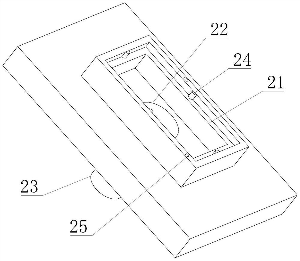
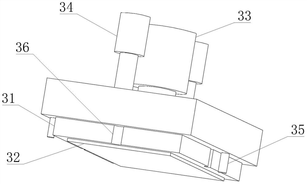
[0040] Such as Figure 1-7 As shown, on the basis of Embodiment 1, the present invention provides a technical solution: preferably, a mold cavity 21 is provided inside the lower mold 2, and a demoulding bottom plate 22 is movably installed at the center of the lower surface of the mold cavity 21, and the demoulding bottom plate The lower surface of 22 is fixedly equipped with demoulding hydraulic column 23, the upper end of model cavity 21 is fixedly installed with limiting column 24 in the middle of the inner wall of lower mold 2, and positioning holes 25 are opened on the front and rear sides of the upper surface of lower mold 2, and two positioning holes 25 Not symmetrical about the lower mold 2, the lower surface of the upper mold 3 is fixedly equipped with a sealing plate 31, the lower surface of the sealing plate 31 is movably installed with a pressing plate 32, and the upper surface of the pressing plate 32 is fixedly installed with a forming hydraulic column 33, and the...
PUM
 Abstract
Description
Claims
Application Information
 - R&D
- Intellectual Property
- Life Sciences
- Materials
- Tech Scout
- Unparalleled Data Quality
- Higher Quality Content
- 60% Fewer Hallucinations
Browse by: Latest US Patents, China's latest patents, Technical Efficacy Thesaurus, Application Domain, Technology Topic, Popular Technical Reports.
© 2025 PatSnap. All rights reserved.Legal|Privacy policy|Modern Slavery Act Transparency Statement|Sitemap|About US| Contact US: help@patsnap.com


