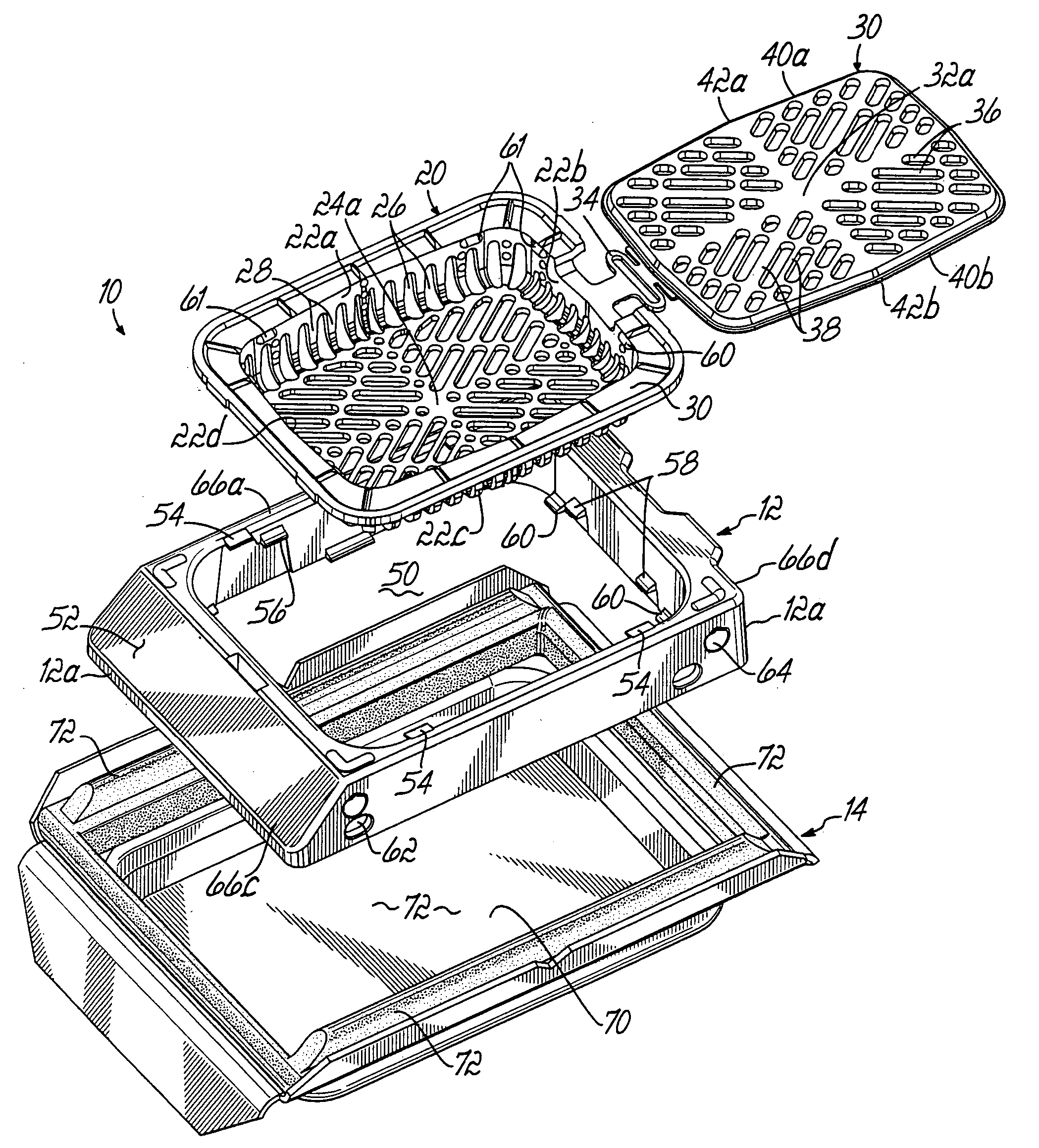
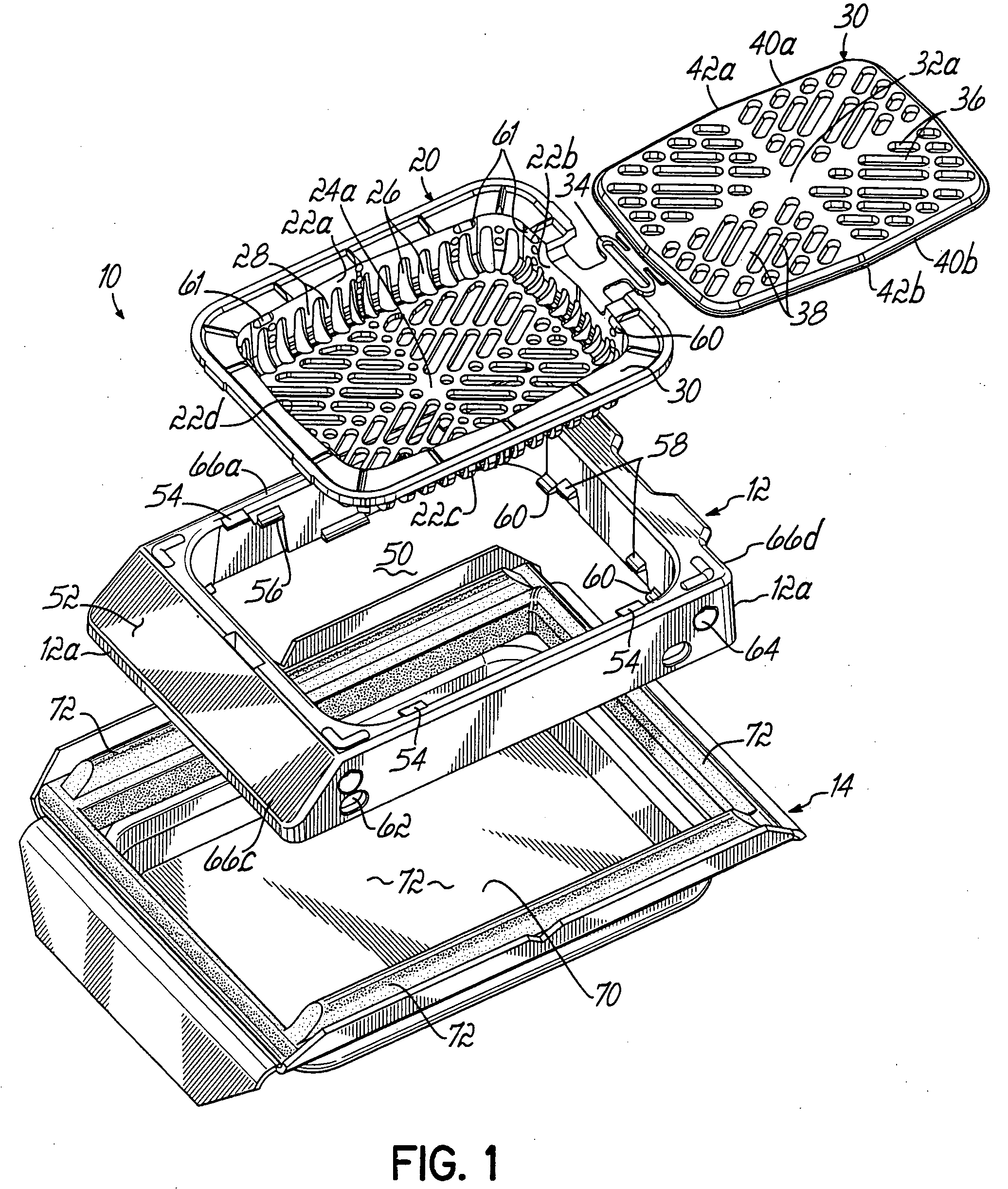
[0011] Generally the invention relates to a cassette for holding a tissue sample during an embedding and microtoming or
slicing process. The cassette includes a body with a bottom wall and a plurality of side walls extending upwardly with respect to the bottom wall to define an
interior space for receiving the tissue sample. The bottom wall and the plurality of side walls are constructed of a material capable of being sectioned in a microtome. Preferably, the cassette material is also resistant to any type of degradation during
processing which would compromise its ability to function in accordance with the invention. In a first aspect of the invention, the plurality of side walls comprise first and second side walls on opposite sides of the bottom wall each including portions angling from approximate midpoints of the first and second side walls toward the other of the first and second side walls on the opposite side of the bottom wall. In the preferred embodiment, the two longest side walls of the four side walls comprising a rectangular cassette are generally V-shaped in a direction away from the interior of the cassette. This presents an apex of the V-shape to the microtome blade, after the
embedding process is complete, which assists with the
cutting action. Specifically, this feature has been found to reduce or prevent the hardened paraffin from breaking or
cracking away from the cassette side
wall material while making slices in the microtome.
[0012] The cassette preferably further includes a lid configured to be coupled with the body for movement between open and closed positions. The lid may be depressed downwardly on top of the tissue sample in the cassette interior. The lid is preferably stiffer than the bottom wall of the cassette. This feature allows the lid to position the tissue sample in the cassette parallel to the bottom of the mold during the
embedding process. More specifically, the stiffer lid pushes the tissue sample and the more flexible bottom wall of the cassette against the rigid bottom of a base mold while the molten paraffin solidifies. This helps ensure that the bottom wall of the cassette can be removed in its entirety during a facing operation in the microtome prior to
slicing the tissue sample, and that the tissue is positioned flatly against the bottom wall of the cassette.
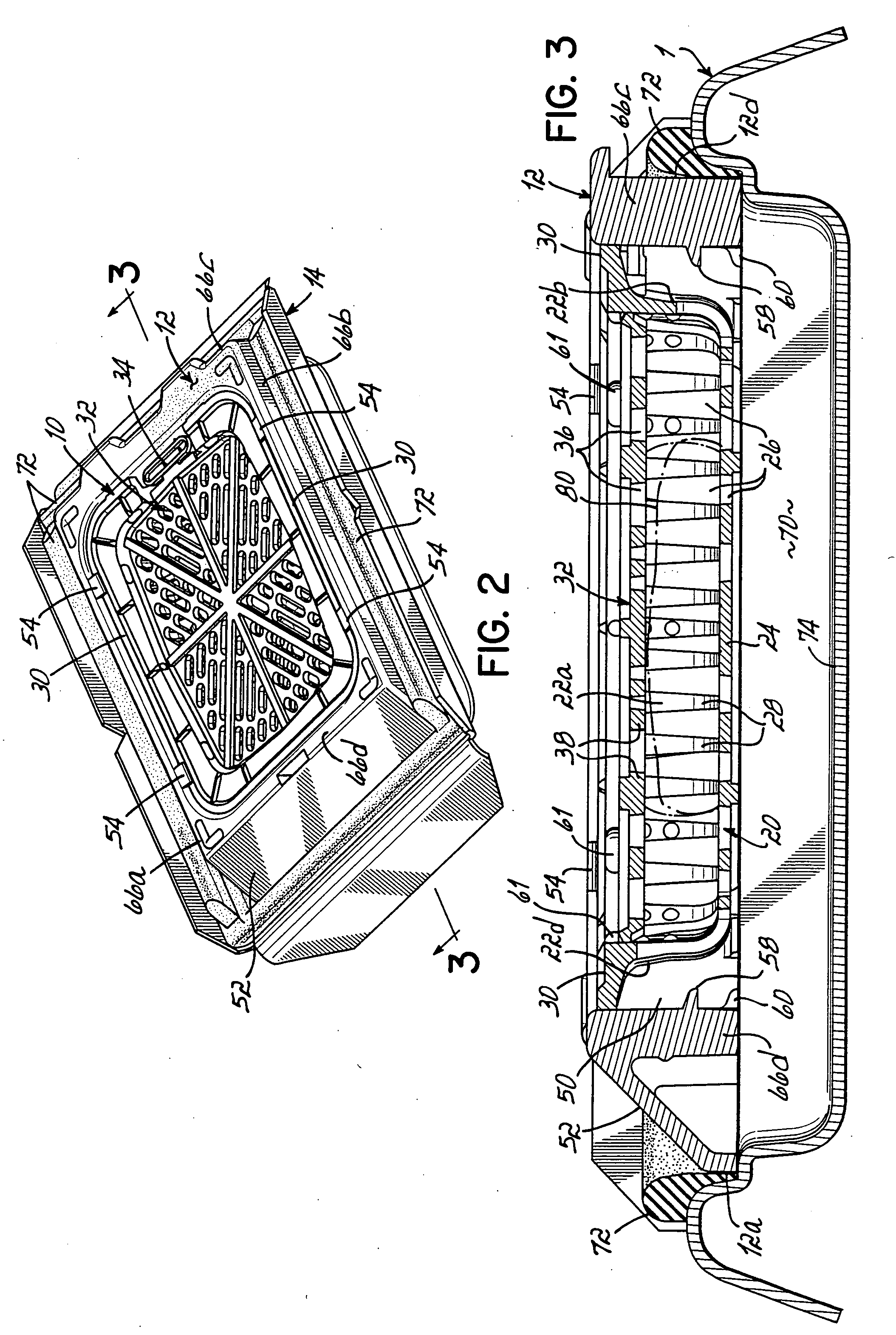
[0013] In another aspect of the invention, the side walls of the cassette are perforated such that there is at least a ratio of about 2.5:1 of open area to
solid material area whereby the solidified paraffin occupies the open area of the side walls. This ratio may be altered by using different materials for the cassette and / or
paraffin embedding media. For instance, a higher molecular weight paraffin or lower moneluculer weight cassette will allow the ratio to vary somewhat. Currently, an
industry standard paraffin (e.g., Sakura VIP
processing /
embedding medium) works best with a ratio of at least about 3.0:1 and, more preferably, at least about 3.5:1. This reduces the amount of cassette material that must be
cut by the microtome blade while taking slices of the tissue and, therefore, increases blade life and quality of the resulting ribboned, embedded tissue samples. In addition this ratio assures that the paraffin is strong enough not to fracture when cut by the microtome blade. Another feature that results in similar advantages involves forming the side walls from ribs and offsetting the ribs of one of the first and second side walls with respect to those of the opposite side wall along the side wall length. Thus, the microtome blade will contact a more uniform amount of the cassette material along its length during each pass. This significantly reduces blade wear while
cutting through the cassette material. Reduced blade wear is advantageous to keeping blade costs under control as the majority of blades used are disposable.
[0014] In another aspect of the invention, the cassette further includes a
flange extending along upper portions of at least two of the side walls. The
flange includes depressions configured to register with detents in a frame during the
tissue embedding process. This increases the
effective height dimension of the cassette interior, thereby allowing more tissue to be placed in the cassette and more passes to be made in the microtome. In this regard each pass of the microtome may only take a 5 micron slice. Therefore, using depressions having a depth, for example, of 0.14″ can allow about 70 more slices to be taken in the microtome.
[0015] The invention further contemplates the various unique assemblies of two or more of the
tissue cassette, frame, and base mold as disclosed herein. With respect to the frame and base mold, for example, structure is provided to physically hold the frame against the base mold. In the preferred embodiment, a seal is provided to perform this holding function and also to prevent leakage of
liquid paraffin from the base mold.
[0017] In one embodiment, the staging device is a rigid member and the stop comprises a fixed stop member coupled for movement with the staging mechanism and configured to stop against an upper surface of the frame. In another embodiment, the device includes a stabilizing mechanism coupled with the
handle and moveable relative to the staging mechanism. The stabilizing mechanism is configured to engage an upper surface of the frame as the staging mechanism moves the cassette from the upper position to the lower position within the frame. In this embodiment, the staging mechanism is normally spring-biased into an upward position and is forced downward against the spring bias when moving the cassette from the upper position to the lower position. The stop in this embodiment further comprises respective surfaces of the
handle and stabilizing mechanism which engage one another when the staging mechanism has placed the cassette into the lower position. The staging devices of this invention ensure that the cassette is fully staged into the base mold, while ensuring that the cassette is not pushed too far through the frame. Moreover, the staging devices ensure that the bottom wall of the cassette and, therefore, the tissue sample, lay flat against the bottom of the base mold. This improves the efficiency and quality of tissue shavings later made in the microtome.

