Linear backflow defoaming filling machine

A filling machine and defoaming technology, used in packaging, bottle filling, liquid bottling, etc., can solve the problems of easy wear, short service life, and inability to effectively ensure normal production.

Inactive Publication Date: 2016-12-21
JIANGSU WEILONG FILLING MACHINERY
View PDF7 Cites 4 Cited by
  • Summary
  • Abstract
  • Description
  • Claims
  • Application Information

AI Technical Summary

Problems solved by technology

The filling head is installed on the lifting shaft but not on the lower part, so the force on the lifting shaft and the bushing is unbalanced, and it is easy to wear, resulting in a short service life. Generally, it takes about 1 month to stop the machine to replace the lifting shaft and bushing. Otherwise, normal production cannot be effectively guaranteed

Method used


Image

  • Linear backflow defoaming filling machine
  • Linear backflow defoaming filling machine
  • Linear backflow defoaming filling machine

Examples


Embodiment Construction

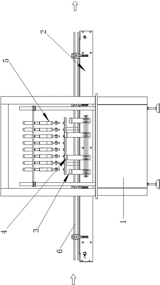
[0017] Such as figure 1 and figure 2 As shown, the linear reflux defoaming filling machine of the present invention includes a frame 1 on which a conveying part 2 is arranged, and the frame 1 is sequentially provided with a cylinder bottle dividing part 3 along the conveying direction of the conveying part 2 1. Positioning part 4 for clamping the mouth of the bottle. A backflow filling head 5 is arranged above the bottle mouth positioning part, and the backflow filling head 5 is fixed on the frame 1 .

[0018] Further, in order to obtain better protection during the conveying process of the filled bottle body, guardrails 6 are arranged on both sides of the conveying part 2 .

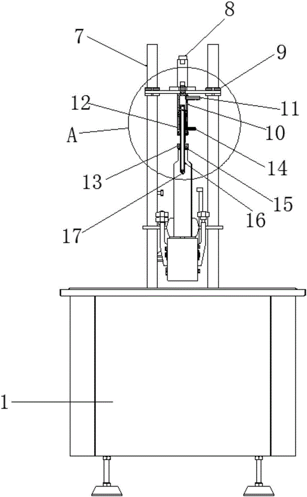
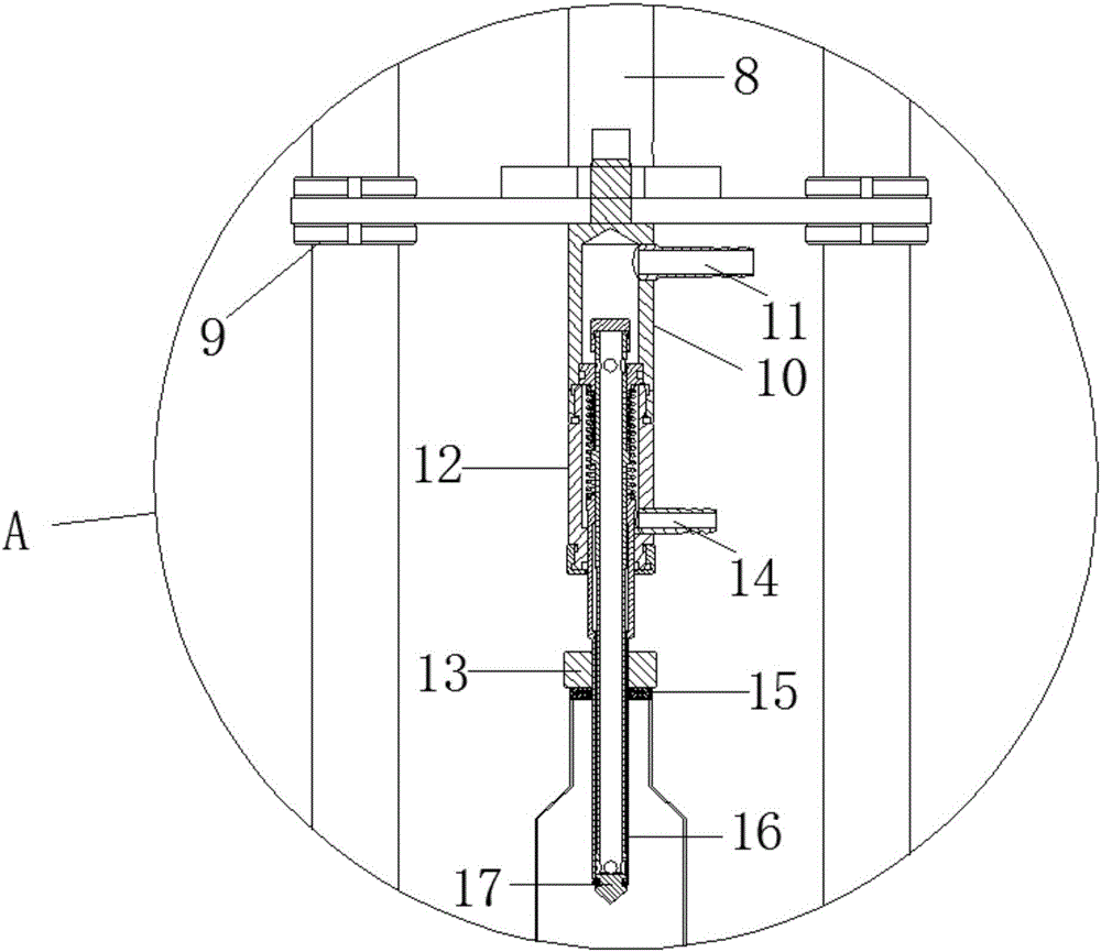
[0019] Further, such as figure 2 and image 3 As shown, the return type filling head 5 includes a filling head driving cylinder 8 arranged on a column 7 . The lower end of the filling head driving cylinder 8 is connected with the valve body 10, and the upper end of the valve body 10 is connected w...


PUM


Abstract

The invention relates to the technical field of defoaming filling machines, in particular to a linear backflow defoaming filling machine. The linear backflow defoaming filling machine comprises a rack; the rack is provided with a conveying component; the rack is provided with an air cylinder bottle distribution components and bottle mouth clamping and positioning components in sequence along the conveying direction of the conveying component; backflow-type filling nozzles are arranged above the bottle mouth clamping and positioning components; and the backflow-type filling nozzles are fixed on the rack. After the structure of the linear backflow defoaming filling machine disclosed by the invention is adopted, when each bottle reaches a filling position, the corresponding filling nozzle presses down a bottle mouth under the drive of an air cylinder; a valve port of the filling nozzle is jacked open by the bottle mouth, and excess liquid after the bottle is filled up flow backs to a liquid storage pot through a liquid return port; the filled bottles are transferred to the next process flow through the bottle outlet end of the conveying belt; filling or retained filling of a high-position liquid storage pot is executed by adopting a sanitary centrifugal pump, and by matching with liquid supplement and backflow of a low-position liquid storage pot, cleaning and installation are convenient.

Description

technical field [0001] The invention relates to the technical field of defoaming filling machines, in particular to a linear backflow defoaming filling machine. Background technique [0002] The linear filling machine is designed for users to fill liquids in pharmaceutical, food, chemical, pesticide and other industries. Piston-type metering pumps are mainly used, and each of them is individually adjusted. Because of its accurate filling volume, reasonable structure, and convenient operation, it can be applied to filling bottles of different materials and specifications. [0003] When the linear defoaming filling machine is filling, it drives the lifting shaft to move up and down through external force, and drives the filling head to complete the filling work. The filling head is installed on the lifting shaft but not on the lower part, so the force on the lifting shaft and the bushing is unbalanced, and it is easy to wear, resulting in a short service life. Generally, it t...

Claims


Application Information

Patent Timeline
Patent Type & Authority Applications(China)
IPC IPC(8): B67C3/26
CPCB67C3/26B67C2003/2671
Inventor 蒋玉华吴继芳周明
Owner JIANGSU WEILONG FILLING MACHINERY
Why Eureka
Try Eureka