Diaphragm type pressure relief valve

A pressure reducing valve and diaphragm type technology, applied in the field of pressure reducing valves, can solve problems such as threats to the personal safety of staff, failure of instruments and equipment to work properly, discontinuous gas supply, etc., to reduce potential safety hazards, simple structure and tightness Good results

Inactive Publication Date: 2019-05-21
扬州市万隆气体有限公司
View PDF0 Cites 0 Cited by
  • Summary
  • Abstract
  • Description
  • Claims
  • Application Information

AI Technical Summary

Problems solved by technology

[0003] The existing working environment that needs to use gas is generally to place a lot of gas cylinders indoors to supply the equipment one by one. The environment where the gas cylinders are concentrated has great potential safety hazards. Some gases are still poisonous and harmful, which seriously threatens The personal safety of the staff, and secondly, the interruption of gas supply will bring huge economic losses, especially the gas supply of most laboratories today is different from the requirements of general factory workshops. Secondly, various analytical instruments such as chromatographs or mass spectrometers require continuous use of gas. The supply of gas must be continuous, and the output pressure must be stable. Fluctuations in gas pressure may cause the equipment to fail to work normally, and discontinuous supply of gas may even cause equipment failure. failure, so the design of the laboratory gas pipeline must be very strict

Method used


Image

  • Diaphragm type pressure relief valve

Examples


Embodiment Construction

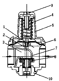
[0009] A diaphragm pressure reducing valve, the valve includes a valve body 1, a connecting rod 2, an inner cavity 3, a spring 4, a valve cover 5, a diaphragm 6, a valve seat 7, a valve core 8, an adjusting nut 9 and a base 10. The air inlet and air outlet are arranged on both sides of the valve body 1, the valve body 1 is in the shape of a round bottle, and the valve core 8 is arranged between the air inlet and the air outlet in the valve body 1 , the base 10 is set on the bottom of the valve body 1, the valve core 8 can move up and down in the base 10, the valve cover 5 is set on the upper part of the valve body 1, and the adjusting nut 9 is set on the valve body 1 top, the lower part of the adjustment nut 9 is connected to the connecting rod 2, the spring 4 is arranged on the connecting rod 2 in the valve cover 5, and the top end of the lower part of the connecting rod 2 is provided with a diaphragm 6. The diaphragm 6 moves up and down in the valve body 1 following the spri...


PUM


Abstract

The invention relates to a diaphragm type pressure relief valve. The valve comprises a valve body, a connecting rod, an inner cavity, a spring, a valve cover, a diaphragm, a valve seat, a valve core,an adjusting nut and a base, an air inlet and an air outlet are formed in both sides of the valve body, the valve body is in a round bottle shape, the valve core is arranged between the air inlet andthe air outlet in the valve body, the base is arranged at the bottom of the valve body, and the valve core can move up and down in the base; and the valve cover is arranged at the upper part of the valve body, the adjusting nut is arranged at the top of the valve body, the lower part of the adjusting nut is connected to the connecting rod, the spring is arranged on the connecting rod inside the valve cover, the diaphragm is arranged at the top end of the lower part of the connecting rod, and the diaphragm moves up and down in the valve body along with the spring and the connecting rod. The diaphragm type pressure relief valve is simple in structure, reducing in safety hazards, convenient to operate, precise in valve opening and closing control, convenient to mount and wash, high in sealingperformance, high in start-and-close speed, stable in operation, and long in service life.

Description

technical field [0001] The invention relates to a pressure reducing valve, in particular to a diaphragm type pressure reducing valve. Background technique [0002] Now some factory workshops and modern laboratories need the design of gas pipelines. The gas supply pipeline system plays an important role in it. Whether its design is reasonable will have a direct impact on the normal operation of the work and the accuracy of laboratory experiment results. A professional and reasonable gas supply pipeline system can greatly reduce potential safety hazards, and facilitate daily inspection and maintenance. [0003] The existing working environment that needs to use gas is generally to place a lot of gas cylinders indoors to supply the equipment one by one. The environment where the gas cylinders are concentrated has great potential safety hazards. Some gases are still poisonous and harmful, which seriously threatens The personal safety of the staff, and secondly, the interruption...

Claims


Application Information

Patent Timeline
Patent Type & Authority Applications(China)
IPC IPC(8): F16K17/20
Inventor 张爱英王飞张爱忠
Owner 扬州市万隆气体有限公司
Why Eureka
Try Eureka