
Compressor and cylinder assembly thereof

An assembly and cylinder technology, applied in the field of compressor supporting components, can solve problems such as cable insulation structure damage, winding heating, hidden dangers of safe and stable operation of equipment, etc., to improve operational reliability and stability, and reduce air intake Effect

Active Publication Date: 2016-12-21
重庆凌达压缩机有限公司
View PDF7 Cites 0 Cited by
  • Summary
  • Abstract
  • Description
  • Claims
  • Application Information

AI Technical Summary

Problems solved by technology

Especially for HVAC equipment such as heat pumps and some special-purpose compressors, due to unstable working conditions, the compressors often work under extreme conditions. , the equipment motor will work und

Method used


Image

  • Compressor and cylinder assembly thereof
  • Compressor and cylinder assembly thereof

Examples


Example Embodiment

[0016] The core of the present invention is to provide a cylinder assembly, which can effectively reduce the operating load of the compressor when the discharge pressure is large and the suction and discharge pressure difference is large; at the same time, it provides a method for applying the above cylinder assembly. Into the compressor.

[0017] In order to enable those skilled in the art to better understand the solution of the present invention, the present invention will be further described in detail below with reference to the accompanying drawings and specific embodiments.

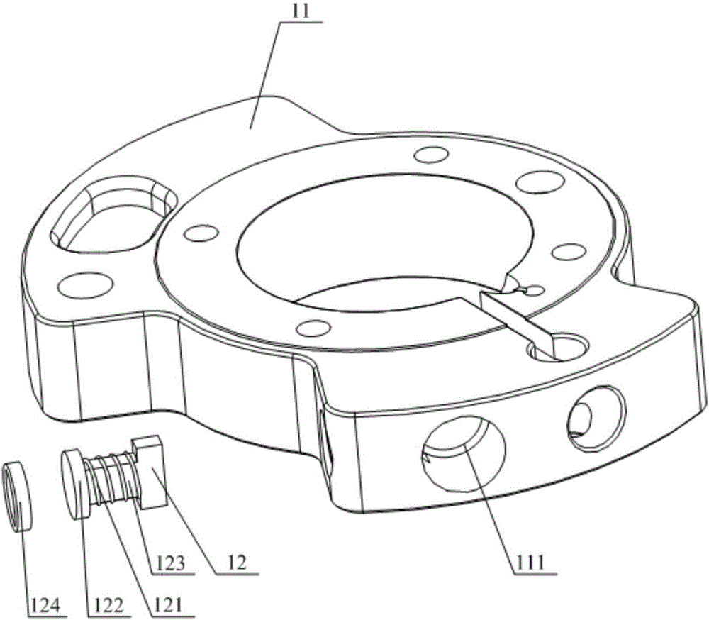
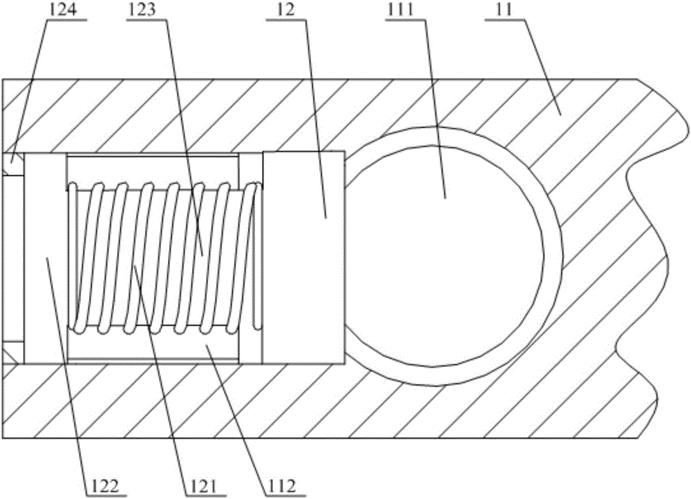
[0018] Please refer to figure 1 with figure 2 , figure 1 It is an exploded view of the structure of the cylinder assembly provided by a specific embodiment of the present invention; figure 2 for figure 1 An enlarged cross-sectional view of the partial structure of the middle suction channel and the valve cavity.

[0019] In a specific embodiment, the cylinder assembly provided by the present invention...


PUM


Abstract

The invention discloses a cylinder assembly. The cylinder assembly comprises a cylinder body, wherein an air suction channel is arranged on the cylinder body, a valve cavity is formed in the inner wall of the air suction channel, a valve is arranged in the valve cavity in a reciprocating motion manner, the movement direction of the valve is perpendicular to the axial direction of the air suction channel, and a driving device capable of driving the valve to extend into the air suction channel is arranged in the valve cavity. The running load of the compressor can be effectively reduced through the cylinder assembly under the conditions of large exhaust pressure and large pressure difference of suction and exhaust pressure. The invention further discloses a compressor applying the cylinder assembly.

Description

technical field [0001] The invention relates to the technical field of compressor supporting components, in particular to a cylinder assembly. The invention also relates to a compressor using the cylinder assembly. Background technique [0002] The cylinder is one of the important components of the compressor, which determines the suction and discharge conditions and operating performance of the compressor. Especially for HVAC equipment such as heat pumps and some special-purpose compressors, due to unstable working conditions, the compressors often work under extreme conditions. , The motor of the equipment will work under overload conditions for a long time. In this case, the winding heats up seriously, and the cable insulation structure is easily damaged, which will cause hidden dangers to the safe and stable operation of the equipment. [0003] Therefore, how to reduce the operating load of the compressor when the discharge pressure is high and the pressure difference ...

Claims


Application Information

Patent Timeline
IPC IPC(8): F04B39/12F04B39/10F04B39/08F04B49/22
CPCF04B39/08F04B39/10F04B39/122F04B49/225
Inventor 龚海涛范少稳
Owner 重庆凌达压缩机有限公司
Learn More