Vehicle power transmission system

A power transmission and vehicle technology, applied in combustion engine, engine control, machine/engine, etc., can solve the problems of operator discomfort, time-consuming, long torque loss time, etc., to achieve easy change steps and reduce discomfort Effect

Active Publication Date: 2016-04-13
FCC KK
View PDF7 Cites 0 Cited by
  • Summary
  • Abstract
  • Description
  • Claims
  • Application Information

AI Technical Summary

Problems solved by technology

[0007] However, in the power transmission device described in the above-mentioned Patent Document 1, after the clutch is disengaged, the speed change operation of the speed change device is performed, that is, the gear sets constituting the shift speed need to perform a shifting step, so the speed change operation takes time. , and at the same time, the so-called torque drop in which the driving force from the engine is not transmitted to the drive wheels takes a long time, and there is a problem of causing discomfort to the operator.

Method used


Image

  • Vehicle power transmission system
  • Vehicle power transmission system
  • Vehicle power transmission system

Examples


Embodiment Construction

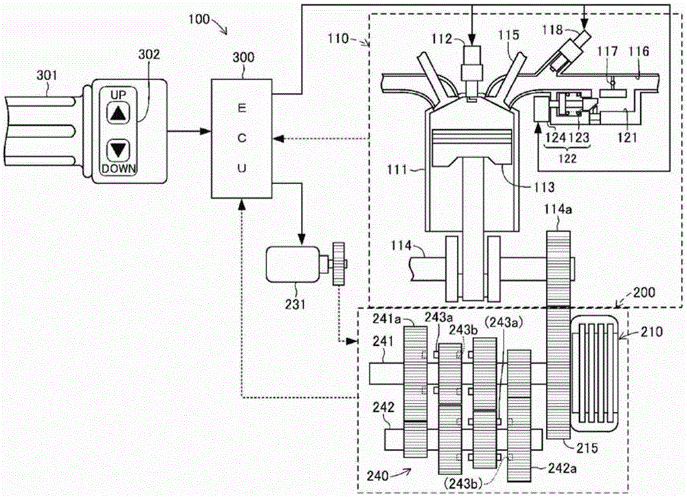
[0024] Hereinafter, an embodiment of the vehicle power transmission system according to the present invention will be described with reference to the drawings. figure 1 This is a block diagram schematically showing the overall schematic configuration of the vehicle power transmission system 100 of the present invention. In addition, in each drawing referred to in this specification, in order to facilitate understanding of this invention, some components are shown schematically, etc. exaggeratedly. Therefore, there may be differences in dimensions, ratios, and the like among the constituent elements. The power transmission system 100 for a vehicle is a group of mechanical devices that transmit the rotational driving force generated by the engine as a prime mover to the drive wheels in a two-wheeled vehicle (so-called motorcycle). perimeter (for example, under the seat cushion or fuel tank).

[0025] (Configuration of Vehicle Power Transmission System 100 )

[0026] The vehic...


PUM


Abstract

Provided is a vehicle power transmission system which quickly performs shift operations in the transmission and is capable of alleviating the operator's discomfort due to so-called torque loss during said shift operations. This vehicle power transmission system (100) is provided with an engine (110) the operation of which is controlled by an ECU (300), a clutch (210) and a transmission (240). The engine (110) is provided with a bypass pathway (121) in a state in which a throttle valve (117) is bypassed by an intake pipe (116) which introduces a fuel-air mixture into a cylinder (111). An idle regulating valve (122) is provided in the bypass pathway (121). The idle regulating valve (122) regulates the amount of air that bypasses the throttle valve (117) and is supplied to the cylinder (111). The ECU (300) reduces the deceleration torque in the transmission (240) by opening the idle regulating valve (122) prior to shift change operations of the transmission (240).

Description

technical field [0001] The present invention relates to a vehicle power transmission system mounted on a self-propelled vehicle such as a two-wheeled vehicle or a four-wheeled off-road vehicle. Background technique [0002] Conventionally, a self-propelled vehicle such as a two-wheeled vehicle or a four-wheeled off-road vehicle has a power transmission device for transmitting the driving force generated by the engine (prime mover) to the drive wheels. The power transmission device is a mechanical device that connects and disconnects the rotating drive shaft (crank shaft) of the engine while changing the number of revolutions of the rotating drive shaft and transmitting it to the driving wheels. It is mainly composed of a clutch and a transmission. Here, the clutch is a mechanical device that transmits the rotational drive force of the rotational drive shaft of the engine to the transmission side while connecting and disconnecting the rotational drive shaft of the engine. In...

Claims


Application Information

Patent Timeline
Patent Type & Authority Patents(China)
IPC IPC(8): F02D41/08F02D9/02
CPCF02D9/1055F02D31/005F02D41/0002F02D41/08Y02T10/40
Inventor 牧田昇司宫地一好千叶良平
Owner FCC KK
Why Eureka
Try Eureka