
Lead frame and a method for producing piezoelectric vibrator, a resin mold construction of a piezoelectric vibrator

A piezoelectric vibrator and lead frame technology, which is applied in the field of radio clocks, can solve the problems of insufficient bending of the outer lead 3, elastic deformation of the outer lead, impossible alignment of the required joints, etc.

Active Publication Date: 2006-12-20
SII CRYSTAL TECH
View PDF0 Cites 2 Cited by
  • Summary
  • Abstract
  • Description
  • Claims
  • Application Information

AI Technical Summary

Problems solved by technology

In the previous process for bending the outer lead 3, the misadjustment of the turning angle difference θ for the outer lead 3 resulted in insufficient bending of the outer lead 3, making it impossible to align the desired bonding point in some cases
[0036] 3. As mentioned above, even a small load can cause elastic deformation of the outer lead 3
[0047] 2. The electrical test process for the surface mount type piezoelectric vibrator 31 requires more measurement time because of the measurement items and measurement accuracy used to ensure the performance characteristics of the surface mount type piezoelectric vibrator 31 in recent years
[0060] The above-mentioned problems are caused by the aggregation of the lead frame 60, thereby suppressing the need in the manufacturing process of the surface mount type piezoelectric vibrator 31

Method used


Image

  • Lead frame and a method for producing piezoelectric vibrator, a resin mold construction of a piezoelectric vibrator
  • Lead frame and a method for producing piezoelectric vibrator, a resin mold construction of a piezoelectric vibrator
  • Lead frame and a method for producing piezoelectric vibrator, a resin mold construction of a piezoelectric vibrator

Examples


no. 1 example

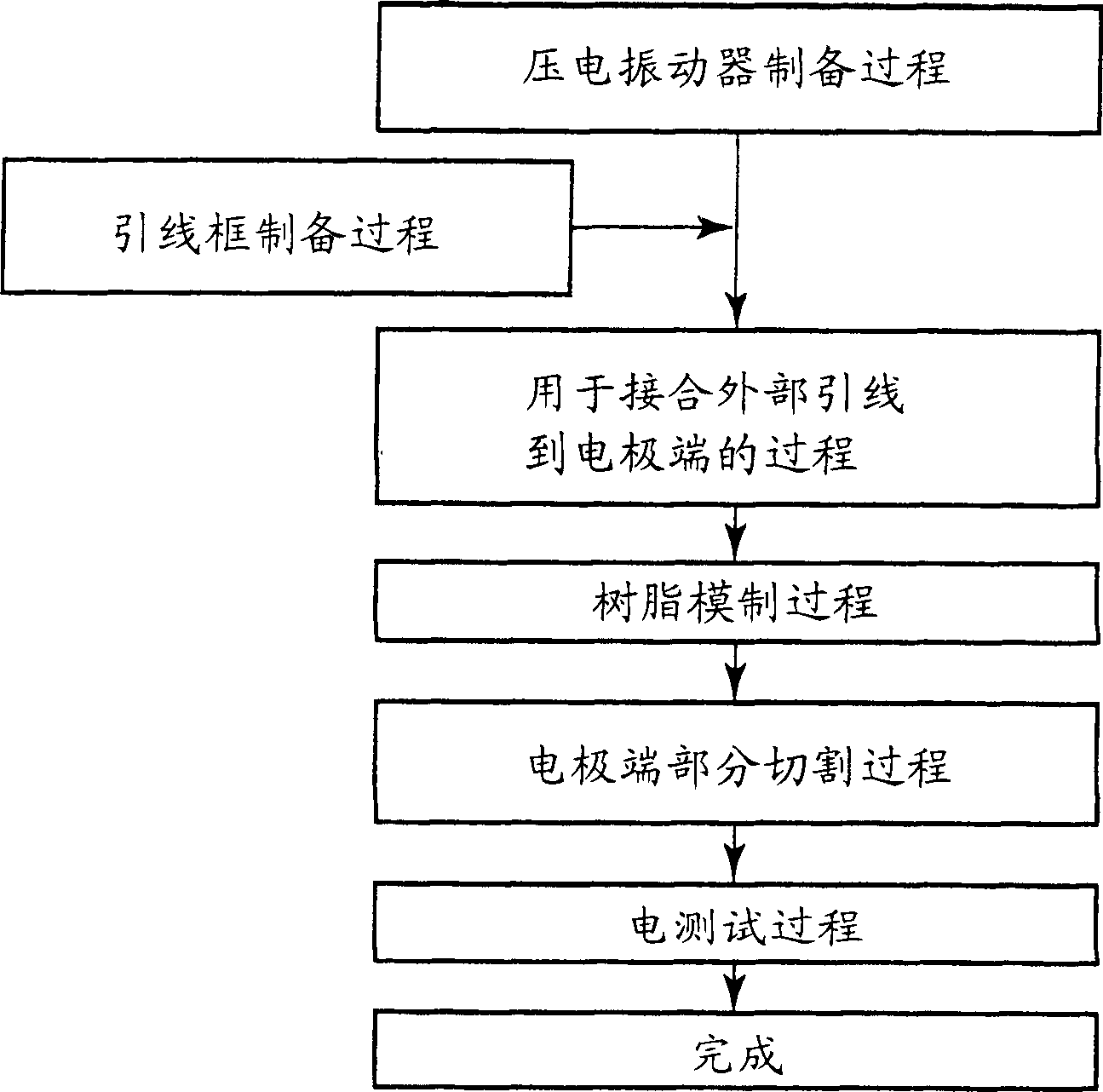
[0183] figure 1 is a flowchart briefly showing the manufacturing process of the surface mount type piezoelectric vibrator according to the first embodiment of the present invention. In order to facilitate understanding of this embodiment, the following process will be described as follows:

[0184] 1. Piezoelectric vibrator preparation process: After cutting and polishing, a quartz crystal sheet is formed from a piezoelectric material. An electrode film required for each quartz crystal plate used as a piezoelectric vibrator is formed on each of its front and rear surfaces, thereby forming a piezoelectric vibrating plate. A piezoelectric vibrating piece is bonded to each sealing end, wherein the sealing end is connected to a dynamic loading plate for the piezoelectric vibrator. The dynamic splint is prepared for the finished piezoelectric vibrator, which are all sealed in the sealed tube.

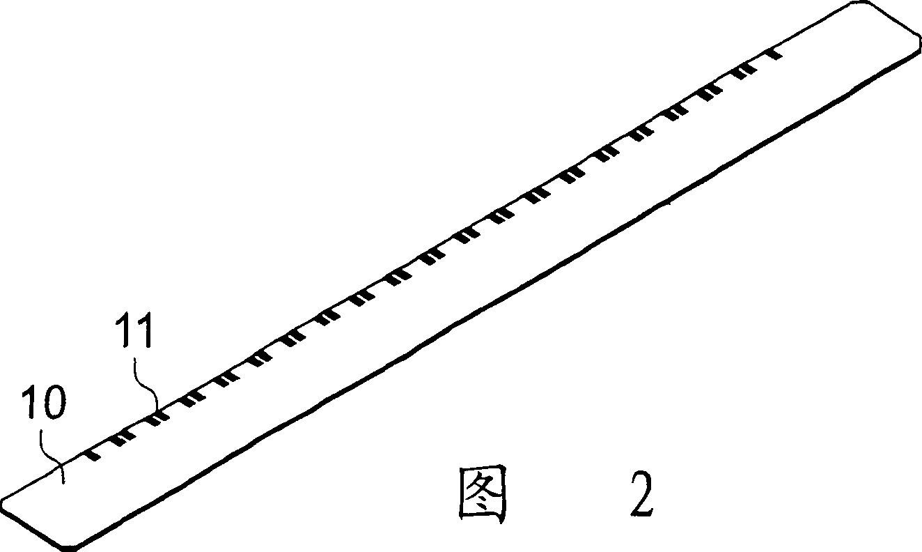
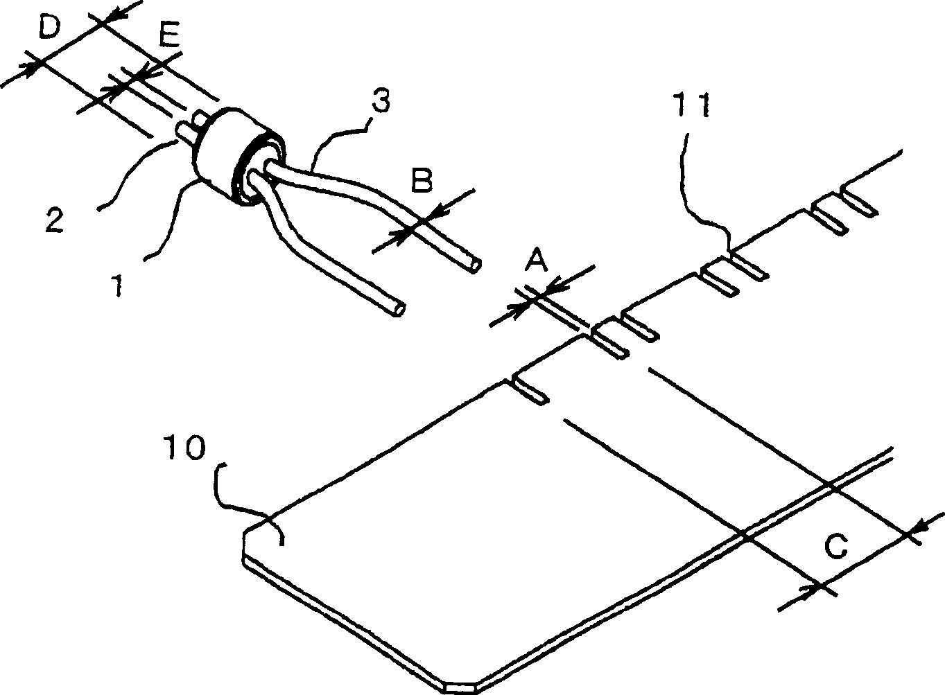
[0185] 2. Lead frame preparation process:

[0186] A lead frame formed with electro...

no. 2 example

[0302] A second embodiment according to the present invention will be described below with reference to FIG. 28 . FIG. 28 is a schematic pattern diagram of an example structure of a tuning-fork type quartz crystal oscillator according to a second embodiment of the present invention. The tuning fork type quartz crystal oscillator 90 uses the above-mentioned surface mount type piezoelectric vibrator 31 as an oscillating plate, and is connected to an integrated circuit.

[0303] In FIG. 28 , a surface mount type piezoelectric vibrator 31 is provided in a predetermined position on a substrate 92 , and an integrated circuit for an oscillator denoted by reference numeral 93 abuts against the surface mount type piezoelectric vibrator 31 . Electronic components 94 such as capacitors are also mounted. These components are electrically connected together by an unillustrated wiring pattern. The mechanical vibration of the vibrating plate of the surface mount type piezoelectric vibrator...

no. 3 example

[0306] A third embodiment of the present invention will be described below. The third embodiment is an example of an electronic unit using a surface mount type piezoelectric vibrator 31 manufactured by the method according to the present invention, wherein the vibrator is connected to a timekeeping section. As an example of an electronic unit, a preferred embodiment of a portable information unit represented by a mobile phone will be described below with reference to the accompanying drawings. Figure 29 is a block diagram functionally showing the structure of the portable information unit according to this embodiment.

[0307] The portable information unit 100 is an improved and improved version of a wrist watch made in the prior art. The portable information unit is similar in appearance to a wristwatch. The portable information unit has a liquid crystal display instead of a clock dial, which shows the current time on the screen. When the portable information unit is used...


PUM


Abstract

A lead frame comprising a pair of side frames having a positioning hole, a section bar bridging between side frames, a frame area partitioned by the side frames and the section bar, a plurality of first lead sections arranged at predetermined intervals in a frame area partitioned by the side frame and the section bar and extending from the section bar, and a plurality of second lead sections arranged at predetermined intervals in a frame area and facing the first lead sections arranged at the same intervals and extending from the section bar, wherein the first lead sections and the second lead sections are each arranged on the lead fame across the width of the lead frame, and wherein the first lead sections face the second lead sections in a longitudinal direction of the lead frame.

Description

technical field [0001] The present invention relates to a lead frame and a method for manufacturing a surface mount type piezoelectric vibrator using the lead frame, a resin molded structure of the piezoelectric vibrator, a surface mount type piezoelectric vibrator, an oscillator having the same, Electronic unit and radio controlled clock. Background technique [0002] Piezoelectric vibrators are indispensable for the manufacture of industrial products such as watches, oscillators, and electronic units. Piezoelectric vibrators are used as timing sources, timing sources, or reference sources for signals. Commonly used piezoelectric vibrator packages include cylindrical packages. The structure of the cylindrical package piezoelectric vibrator will be described below with reference to the drawings. [0003] Figure 31 is an exploded perspective view of the structure of a cylindrical package piezoelectric vibrator. Such as Figure 31 As shown, a cylindrical package piezoelec...

Claims


Application Information

Patent Timeline
Patent Type & Authority Applications(China)
IPC IPC(8): H03H3/02H03H9/02H03H9/19
CPCH01L2924/0002H03H9/0519H03H3/02H01L2924/00
Inventor 佐藤正行神山敦寺屋顺次石井和纪清水敏志
Owner SII CRYSTAL TECH
Learn More