Battery pack temperature control/power feed system

A temperature control and power supply system technology, applied to secondary batteries, circuits, electrical components, etc., can solve the problems of not having the charging function of the battery itself, poor heating and cooling efficiency, and greatly increased costs to achieve cooling efficiency Excellent, improved battery life, and prevents damage from occurring

Active Publication Date: 2018-11-23
LEADING EDGE ASSOC CO LTD +1
View PDF17 Cites 2 Cited by
  • Summary
  • Abstract
  • Description
  • Claims
  • Application Information

AI Technical Summary

Problems solved by technology

[0048] However, in the battery system 300 of the aforementioned Patent Document 3, the joint surfaces of the inner heat receiving plates 324, 326 must be formed across the entire length of the longitudinal direction of the inner heat receiving plates 324, 326 to accommodate the heat pipes 314a to The grooves 336a, 336b in the semicircular cross-section of 314c are used to arrange the heat pipes 314a to 314c, the structure is complicated, the size becomes larger, and the cost also greatly increases
[0049] In addition, in the battery system 300 of the aforementioned Patent Document 3, the frame 302, the air inlet pipe 304, the cooling medium passage 322, the air outlet pipe 308, etc. must be installed, which complicates the structure, increases the size, and greatly increases the cost.
[0050] In addition, since the heat pipes 314a to 314c are arranged only on the joint surfaces of the inner heat receiving plates 324 and 326, the battery modules 310a to 310f are cooled linearly by the heat pipes 314a to 314c, not in a planar manner. Heating and cooling battery modules 310a to 310f, poor heating and cooling efficiency
[0051] In addition, if Figure 13 As shown in (A), since the wind introduced by the fan 306 does not directly contact the fin 318, the thermoelectric element member 316, and the heat receiving plate 312 directly, but contacts from the side, the heating and cooling efficiency is poor.
[0052] In addition, in the battery system 400 of the aforementioned Patent Document 4, since a plurality of heat pipes 406 are only arranged in the longitudinal direction between a plurality of battery cells 402 arranged in a vertical and horizontal manner, the heat pipes 406 and The linear cooling structure of the battery cell 402 is not heating and cooling the planar battery cell 402 in a planar manner, and the heating and cooling efficiency is poor
[0053] In addition, in the battery system 400 of the above-mentioned Patent Document 4, the heater and the fins 410 are arranged at the opposite end of the battery cell 402 in the longitudinal direction, so the heating and cooling efficiency is poor.
[0054] In addition, the battery systems 100 to 400 of the aforementioned Patent Document 1 to the aforementioned Patent Document 4 do not have the function of charging the battery cells themselves.

Method used


Image

  • Battery pack temperature control/power feed system
  • Battery pack temperature control/power feed system
  • Battery pack temperature control/power feed system

Examples


Embodiment Construction

[0154] Hereinafter, embodiments (examples) of the present invention will be described in more detail with reference to the drawings.

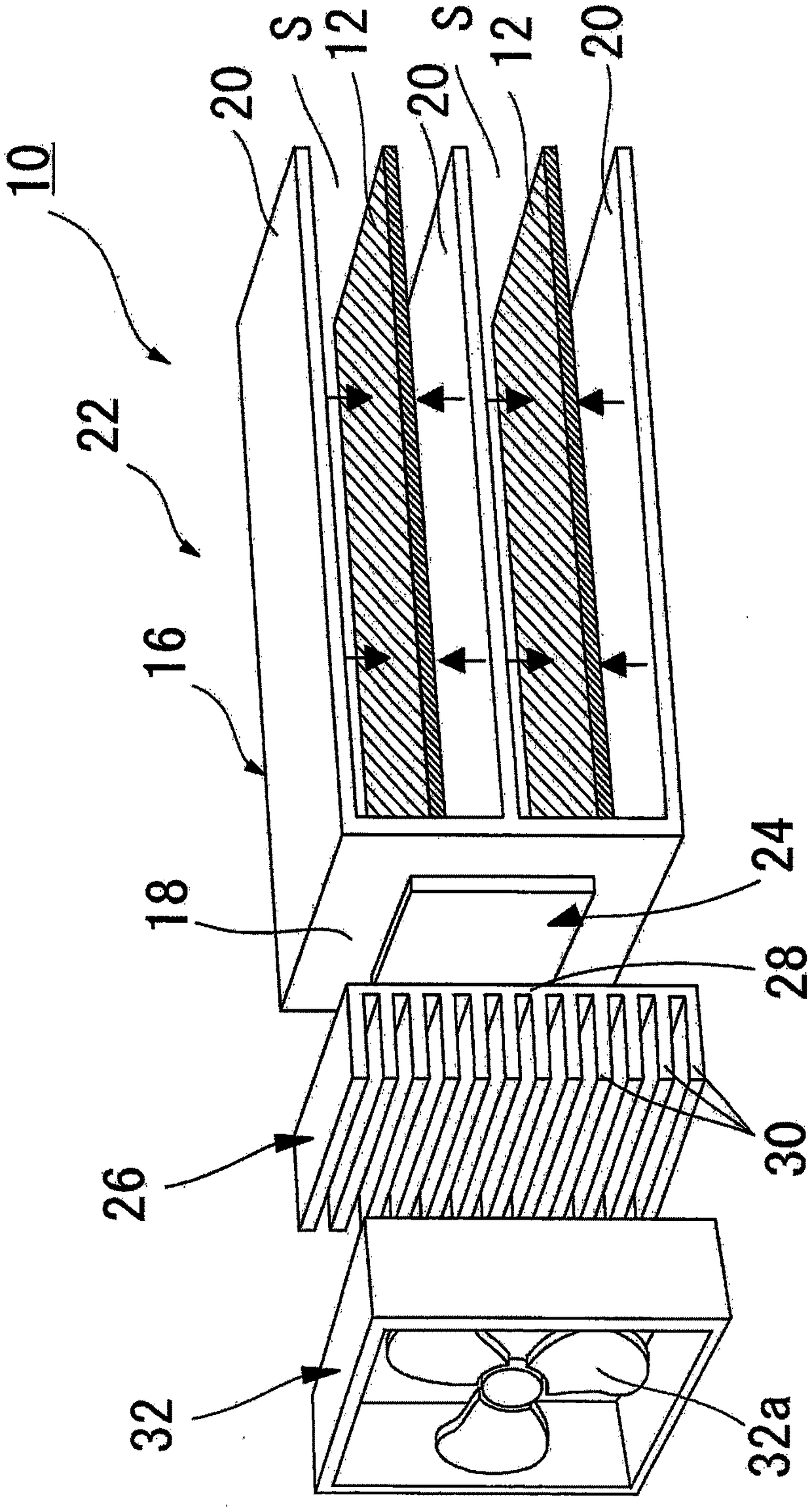
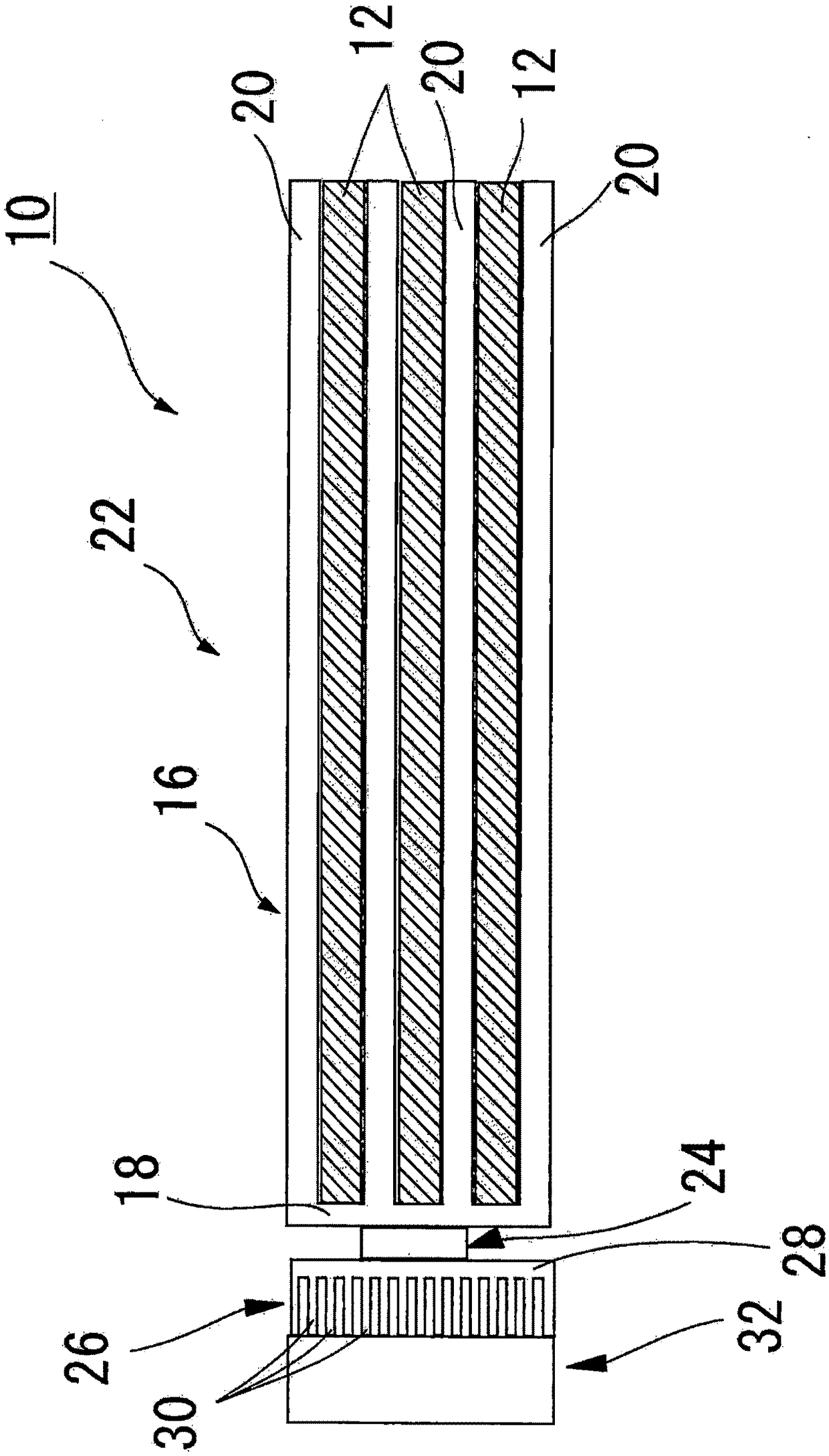
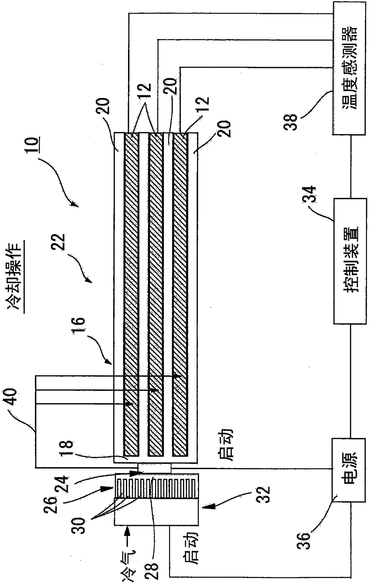
[0155] figure 1 It is a three-dimensional exploded view conceptually showing the battery pack temperature control and power supply system of the present invention, figure 2 for figure 1 The cross-sectional view of the temperature control and power supply system of the battery pack, image 3 A block diagram of the battery pack temperature control and power supply system for explaining the operating state of the battery pack temperature control and power supply system when the battery part is cooled in the present invention, Figure 5 A block diagram of the battery pack temperature control and power supply system for explaining the operating state of the battery pack temperature control and power supply system when the battery part is heated in the present invention, Figure 6 A block diagram of the battery pack temperature control and powe...


PUM


Abstract

To provide a battery pack temperature control/power feed system in which a battery cell can be heated or cooled in a planar configuration, said system having highly exceptional heating efficiency andcooling efficiency, stable battery performance, a small number of components, and an uncomplicated structure, while making it possible to reduce the size and thickness as well as cost. A battery packtemperature control/power feed system 10 provided with: a battery part 22, which is formed by laminating a plurality of battery cells 12 and a plate-shaped vapor chamber 16 interposed between the battery cells 12; a thermoelectric element 24 positioned so as to adhere tightly to the end surface of one end of the vapor chamber 16 (lateral vapor chamber 18); and a heat sink part 26 equipped with a plurality of fins 30 that are formed extending at a predetermined spacing from each other, the end surface of the heat sink part 26 adhering tightly to the thermoelectric element 24; and a fan part 32positioned facing the fins 30 of the heat sink part 26.

Description

technical field [0001] The present invention relates to battery pack (batterypack) temperature control, power supply system (system), such as electric vehicles (Electric Vehicle; EV), hybrid vehicles (Hybrid Vehicle; HV), plug-in hybrid vehicles (Plug-inHybridVehicle; PHV), etc. Battery pack temperature control and power supply systems used in various battery-driven devices equipped with batteries such as nickel metal hydride batteries and lithium ion batteries. [0002] In particular, the present invention relates to a battery pack temperature control and power supply system capable of heating, cooling, and charging battery cells in the above-mentioned battery pack temperature control and power supply system. Background technique [0003] In the prior art, as a battery system for cooling the above-mentioned battery, a battery system disclosed in Patent Document 1 (Japanese Patent No. 5625115) has been proposed. [0004] Figure 11 (A) is a perspective view of the battery s...

Claims


Application Information

Patent Timeline
Patent Type & Authority Applications(China)
IPC IPC(8): H01M10/6572H01M10/613H01M10/615H01M10/647H01M10/6551H01M10/6555H01M10/6563
CPCH01M10/613H01M10/615H01M10/647H01M10/6551H01M10/6555H01M10/6563H01M10/6572Y02E60/10
Inventor 黄国书和田二郎古瑞维许·艾力克斯
Owner LEADING EDGE ASSOC CO LTD
Why Eureka
Try Eureka