
Heat pump system

A heat pump system and heat exchanger technology, applied in the field of heat pump systems, can solve problems such as site restrictions, heat pump system installation and practical differences, inconvenience, etc., to avoid damage such as frozen pipes, save installation space, and improve safety performance Effect

Inactive Publication Date: 2016-12-21
CHONGQING MIDEA GENERAL REFRIGERATING EQUIP +1
View PDF9 Cites 0 Cited by
  • Summary
  • Abstract
  • Description
  • Claims
  • Application Information

AI Technical Summary

Problems solved by technology

[0002] In the related art, since the heat pump system generally only has a unit that only meets the cooling and / or heating requirements (the unit includes a compressor, a control device, a heat exchanger, a shell-and-tube heat exchanger, and a throttling device), the user needs to Re-equip auxiliary equipment such as water pumps and flow controllers outside the connecting pipes reserved by the unit, which caused great inconvenience to users
Moreover, the design and installation of a set of auxiliary equipment such as water pumps and flow controllers matching the unit is relatively professional and complicated for users, and in actual use, the installation of auxiliary equipment such as water pumps and flow controllers is easily affected by Limited space, very inconvenient to install
In addition, the procurement of non-standard parts of the project is complicated, random selection and poor universal type, which have great differences in the installation and practicality of the entire heat pump system, and it is difficult to ensure the efficient operation of the heat pump system

Method used


Image

  • Heat pump system

Examples


Embodiment Construction

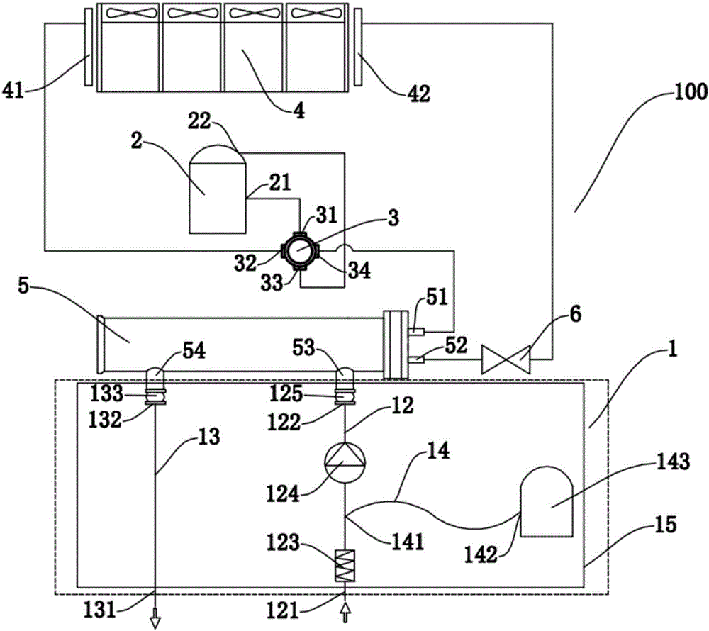
[0031] Embodiments of the present invention are described in detail below, examples of which are shown in the drawings, wherein the same or similar reference numerals designate the same or similar elements or elements having the same or similar functions throughout. The embodiments described below by referring to the figures are exemplary only for explaining the present invention and should not be construed as limiting the present invention.

[0032] In the description of the present invention, it should be understood that the orientations or positional relationships indicated by the terms "middle", "upper", "lower" and the like are based on the orientations or positional relationships shown in the drawings, and are only for the convenience of describing the present invention and simplified descriptions, rather than indicating or implying that the device or element referred to must have a specific orientation, be constructed and operate in a specific orientation, and thus shoul...


PUM


Abstract

The invention discloses a heat pump system. The heat pump system comprises a compressor, a control device, a heat exchanger, a shell and tube heat exchanger, a throttling device and a hydraulic power module. The compressor is provided with an air suction opening and an air exhaust opening. The control device is provided with a first connector, a second connector, a third connector and a fourth connector, the first connector is connected with the air suction opening, and the third connector is connected with the air exhaust opening. The first end of the heat exchanger is connected with the second connector. The first end of the shell and tube heat exchanger is connected with the fourth connector. A heat exchange water inlet and a heat exchange water outlet are formed in the shell and tube heat exchanger. The throttling device is arranged between the second end of the heat exchanger and the second end of the shell and tube heat exchanger. The hydraulic power module is provided with a water inflowing channel and a water outflowing channel. The first end of the water inflowing channel is provided with a water inflowing connector connected with the heat exchange water inlet, and the second end of the water inflowing channel is provided with a water inlet. The first end of the water outflowing channel is provided with a water outflowing connector connected with the heat exchange water outlet, and the second end of the water outflowing channel is provided with a water outlet. A water pump is arranged on the water inflowing channel. According to the heat pump system, the assembling efficiency is high, and installation is convenient.

Description

technical field [0001] The invention relates to the technical field of refrigeration and heating, in particular to a heat pump system. Background technique [0002] In the related art, since the heat pump system generally only has a unit that only meets the cooling and / or heating requirements (the unit includes a compressor, a control device, a heat exchanger, a shell-and-tube heat exchanger, and a throttling device), the user needs to The auxiliary equipment such as water pumps and flow controllers are reconfigured outside the connecting pipes reserved by the unit, which causes great inconvenience to users. Moreover, the design and installation of a set of auxiliary equipment such as water pumps and flow controllers matching the unit is relatively professional and complicated for users, and in actual use, the installation of auxiliary equipment such as water pumps and flow controllers is easily affected by The site is limited and the installation is very inconvenient. In ...

Claims


Application Information

Patent Timeline
IPC IPC(8): F25B29/00F25B41/04F25B41/06F25B41/30
CPCF25B29/003F25B41/37F25B41/30F25B41/20
Inventor 刘冰杨崇银
Owner CHONGQING MIDEA GENERAL REFRIGERATING EQUIP
Learn More