
Power distribution method and system in electronic chip

A technology of electronic chip and distribution method, which is applied in the electronic field, can solve problems such as the inability to reduce the power of multi-core chips, and achieve the effect of reducing power and reducing the number of threads

Inactive Publication Date: 2016-12-21
李媛媛
View PDF2 Cites 0 Cited by
  • Summary
  • Abstract
  • Description
  • Claims
  • Application Information

AI Technical Summary

Problems solved by technology

[0004] A power distribution method in an electronic chip is provided, which solves the shortcomings of the prior art that the power reduction of multi-core chips cannot be realized

Method used


Image

  • Power distribution method and system in electronic chip
  • Power distribution method and system in electronic chip

Examples


Embodiment Construction

[0025] The following will clearly and completely describe the technical solutions in the embodiments of the present invention with reference to the accompanying drawings in the embodiments of the present invention. Obviously, the described embodiments are only some, not all, embodiments of the present invention. Based on the embodiments of the present invention, all other embodiments obtained by persons of ordinary skill in the art without making creative efforts belong to the protection scope of the present invention.

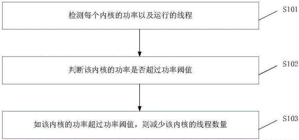
[0026] refer to figure 1 , figure 1 It is a flowchart of a power distribution method in an electronic chip provided by the first preferred embodiment of the present invention. The method is completed by the electronic chip. The method is as follows figure 1 shown, including the following steps:

[0027] Step S101, detecting the power of each core and running threads;

[0028] Step S102, judging whether the power of the core exceeds a power threshold;

[00...


PUM


Abstract

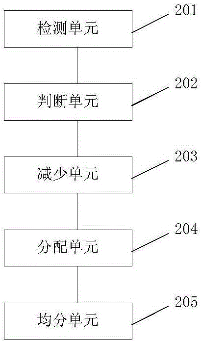
The invention provides a power distribution method and system in an electronic chip. The method comprises the following steps of detecting the power and operational threads of each inner core; judging whether the power of the inner core exceeds a power threshold value or not; if the power of the inner core exceeds the power threshold value, decreasing the number of threads of the inner core. The power distribution method and device have the advantage of effectively lowering power.

Description

technical field [0001] The invention relates to the field of electronics, in particular to a power distribution method and system in an electronic chip. Background technique [0002] Chip, English is Chip; chipset is Chipset. A chip generally refers to the carrier of an integrated circuit, and is also the result of the design, manufacture, packaging, and testing of an integrated circuit. It is usually an independent whole that can be used immediately. The two words "chip" and "integrated circuit" are often used together. For example, in common discussion topics, integrated circuit design and chip design have the same meaning, and the chip industry, integrated circuit industry, and IC industry often have the same meaning. . In fact, the two terms are related as well as different. Integrated circuit entities often exist in the form of chips, because integrated circuits in a narrow sense emphasize the circuit itself, such as a phase-shift oscillator that is as simple as only...

Claims


Application Information

Patent Timeline
Patent Type & Authority Applications(China)
IPC IPC(8): G06F9/50G06F11/30
CPCG06F9/5044G06F11/3062G06F2209/5018G06F2209/5022G06F2209/508Y02D10/00
Inventor 李媛媛
Owner 李媛媛
Learn More