[0025] In order to further understand the content, features, and effects of the present invention, the following embodiments are exemplified, and are described in detail below with the accompanying drawings.
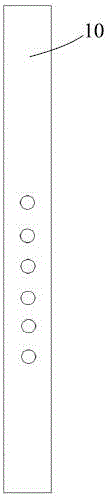
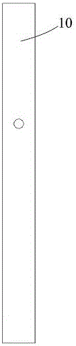
[0026] figure 1 with 2 It is a schematic front view and rear view of a pipe body of a vertical blown wind instrument in the prior art. The wind instrument is typically a traditional Chinese national instrument, such as flute, clarinet, cucurbit flute, etc. In order to avoid obscuring the present invention, other details of the wind instrument, such as blow holes, etc., are not described. These details are different for different instruments. For example, the shape or position of the blow holes of different wind instruments may be different. But when figure 1 with 2 The wind instrument shown does not have parts such as mouthpieces and reeds.
[0027] Such as figure 1 As shown, the wind instrument has a tube body 10, and there are several sound holes (usually 5 or 6) on the front of the tube body 10. In addition, such as figure 2 As shown, the back of the tube body 10 also has a sound hole. The position of the sound hole on the back is higher than the sound holes on the front of the tube body 10. By opening and closing any one or more of these sound holes with your fingers, you can play tones with different pitches. Those skilled in the art can understand that the pitch largely depends on the sound hole with the highest position among the opened sound holes. The back sound hole at the highest point is usually opened and closed by the thumb of a hand, and the highest sound hole in the front sound hole is usually opened and closed by the index finger of the hand. The lowest sound hole in the front sound hole is usually opened and closed by the ring finger of the other hand. Due to the structural limitation of the above-mentioned prior art wind instruments, the sound range is relatively narrow, even if additional sound holes are added, there are no other fingers for control, and the sound is relatively sharp, not very pleasing, or unable to produce sound.
[0028] image 3 with 4 It is a schematic front view and a rear view of an embodiment of the inner cone type wind instrument (the inner cone type saree) of the present invention. It should be noted, image 3 with 4 In order to avoid affecting the description of the sound hole position, some buttons or sliding keys located on part of the sound hole are not shown, which will be introduced in the following.
[0029] The inner cone-shaped saree includes a mouthpiece 101 at the upper end, a tube body 102 at the middle, and a bell mouth 103 at the lower end.
[0030] The mouthpiece 101 includes a fastener 105 for fixing the reed 104 to the mouthpiece 101. in image 3 with 4 The fastener 105 is shown in a form similar to a wheel tyre, but it should be noted that the fastener 105 can take any possible form, including screws, buckles, etc., as long as it can connect the mouthpiece 101 and the whistle The pieces 104 can be fixed together. In addition, it is also possible to fix the reed 104 to the mouthpiece 101 through the mouthpiece 101 itself by designing the shape of the mouthpiece 101. For example, the mouthpiece 101 is designed with a slot that can be adapted to the reed 104, so that this can be omitted. Fastener 105. In addition, although the reed 104 is shown on the back side of the wind instrument or mouthpiece in the figure, it may also be located on the front side of the wind instrument or mouthpiece. The addition of the mouthpiece 101 and the reed 104 can make the volume of the wind instrument of the present invention larger and the sound more pleasing.
[0031] versus figure 1 with 2 Compared with the wind instruments in the prior art shown in image 3 with 4 The tube body 102 of the embodiment shown in FIG. 2 has similar sound holes 11, 12, 13, 14, 15, 16 on the front, and a sound hole 22 on the back.
[0032] but, image 3 with 4 The side of the upper part of the tube body 102 in the embodiment shown in FIG. 2 additionally has an overtone hole 21, and the position of the overtone hole 21 is higher than the position of the sound hole 22. Since the overtone hole 21 is arranged on the side of the upper part of the pipe body 102, it can be controlled by the corresponding button 23 by the mouth part of the hand during performance, without the need for finger control. Among them, in a natural state, the button 23 closes the overtone hole 21. When the button 23 is pressed on the mouth of the hand, the overtone hole 21 is opened. In addition, there are two oblique side sound holes 18 and 19 on the oblique side of the lower part of the tube body 102, which can be used by the little finger to press buttons or sliding keys (in order to clearly show the positions of the oblique side sound holes 18 and 19, not shown Corresponding keys or sliding keys) to control, which will be introduced below.
[0033] In addition, as mentioned above, due to the structural limitation of the wind instrument in the prior art, even if these additional sound holes can be added, the sound is relatively sharp, not very pleasing, or unable to produce sound. In the present invention, through the specially designed tube body 102 structure (see below for details) and the addition of the mouthpiece 101 to the tube body 102, these newly added overtone holes 21 and two oblique side tone holes 18 and 19 It can produce a sound with sufficient volume and pleasant to the ear, thus expanding its range of sound.
[0034] Figure 5 Shows in detail image 3 with 4 中的管体102。 In the tube body 102. Specifically, in Figure 5 The left side of shows a longitudinal sectional view of the tube body 102, wherein the top plane of the tube body 102 is shown by A, and the bottom plane of the tube body 102 is shown by B. in Figure 5 The right side shows the cross-sectional views of the tube body 102 in the top plane A and the bottom plane B, respectively. The pipe body 102 has an inner wall 201 and an outer wall 202. The inner wall 201 of the tube body 102 constitutes a tube with a certain taper, that is, the cavity 203 surrounded by the inner wall 201, the top plane A and the bottom plane B is a truncated cone, and the diameter of the cross section of the cavity 203 (also That is, the inner diameter of the tube body 102 gradually increases from the top A to the bottom B.
[0035] After repeated practice, the inventor has determined the appropriate inner wall taper range of the tube body 102 when the overtone hole 21 of the present invention is used. The inner wall taper range is such that every extension of the tube body 102 length is 48mm-68mm (preferably In the case of 53 mm-63 mm, more preferably 58 mm), the inner diameter of the tube body 102 (that is, the diameter of the cross section of the inner wall 201) is increased or decreased by 1 mm.
[0036] By combining the above-mentioned overtone hole 21 and the taper range of the inner wall, the same tone hole corresponds to two different sounds when the overtone hole 21 is opened and closed. One of the sounds (when the overtone hole 21 is opened) is higher than the other ( When the overtone hole 21 is closed) is 11 degrees higher. For details, see the attachment below Image 6 Related description.
[0037] The length of the tube body 102 may be 300 mm-420 mm, preferably 360 mm. The minimum value of the inner diameter of the tube body 102 (that is, the diameter of the inner wall 201 at the top plane A) may be a value between 9 mm and 15 mm, preferably 12.3 mm.
[0038] When the minimum value of the inner diameter of the tube body 102 is 12.3 mm, the length of the tube body 102 is 360 mm, and the inner diameter of the tube body 102 increases by 1 mm for every 58 mm increase in the tube body 102, image 3 with 4 The diameters of the sound holes 11, 12, 13, 14, 15, 16, 18, 19, 22 are preferably 7.5mm, 8mm, 8mm, 7.5mm, 8mm, 9mm, 10mm, 10mm, 7.5mm, respectively.
[0039] The outer wall 202 of the tube body 102 can also constitute a tube with a certain taper, that is, the part surrounded by the outer wall 202, the top plane A and the bottom plane B is a truncated cone, and the cross-sectional diameter of this part (that is, The outer diameter of the tube body 102) gradually increases from the top A to the bottom B. In a preferred embodiment, the taper of the truncated cone defined by the outer wall 202 is the same as the taper of the truncated cone defined by the inner wall 201. In other embodiments, the taper of the two may be different. In another embodiment, the outer wall 202 may be in the shape of a bamboo joint, rather than a strictly tapered tube.
[0040] Through the taper setting of the inner wall 201 and the overtone hole 21, it is possible to achieve as Image 6 The interval shown. Specifically, a solid circle on the tube body corresponds to each sound hole on the front and oblique sides of the tube body, and a dotted circle on the tube body corresponds to a sound hole on the back of the tube body. Image 6 The left side shows the corresponding pronunciation of each sound hole when the overtone hole 21 is closed (as understood by those skilled in the art, it means that the sound hole is open and each sound hole above it (not involving the overtone hole 21) ) When it is closed), Image 6 The right side shows the corresponding pronunciation of each sound hole when the overtone hole 21 is opened (as understood by those skilled in the art, it means that the sound hole is opened and each sound hole above it (not involving the overtone hole 21). ) Pronunciation when closed). The tube sound when the overtone hole 21 is closed (that is, the sound when all the sound holes are closed) is bass 3. The tube sound when the overtone hole 21 is opened (that is, the sound when all the sound holes except the overtone hole 21 are closed) is the midrange 6. So like Image 6 As shown, it can achieve a large range from bass 3 to super treble 1 (close to three 8 degrees). Moreover, the individual pronunciations in this range are pleasant to the ears and have sufficient volume.
[0041] It should be noted that the pronunciation of each sound hole described above is only used as an example, and the tube sound when the overtone hole 21 is closed is set to bass 3. As understood by those skilled in the art, the drum sounds can be set to different sounds. According to the different tube sound settings, each sound hole can correspond to different pronunciations. For example, if the tube sound when the overtone hole 21 is closed is set to Bass 5, the corresponding interval is from Bass 5 to Super Tweeter 2. # Among them, those skilled in the art can derive the corresponding pronunciation of each sound hole accordingly.
[0042] Figure 7 Shows in detail image 3 with 4 The mouthpiece 101 and the tube body 102 of the inner cone wind instrument in, wherein the mouthpiece 101 and the tube body 102 are handed over near plane A. Tube 102 and Figure 5 It is the same as shown in the above, so I won’t repeat it. The mouthpiece 101 is divided into two parts, the inner cone part below the plane C and the mouthpiece part above the plane C. The inner tapered tube part is interfaced with the upper part of the tube body 102, and at the interface, the two preferably have the same inner diameter. Preferably, the inner wall of the inner tapered tube portion also constitutes a tube with a certain taper, that is, the cavity surrounded by the inner wall 205, plane A and plane C is a truncated cone, and the diameter of the cross section of the cavity (That is, the inner diameter of the inner cone portion) gradually increases from the top C to the bottom A. More preferably, the taper of the inner wall of the inner tapered tube portion is the same as the taper of the inner wall of the tube body 102, that is, the inner wall of the inner tapered tube portion and the inner wall of the tube body 102 together define a truncated cone. Preferably, the length of the inner cone portion is 50 mm, and the total length of the mouthpiece 101 is 73 mm.
[0043] Figure 7 The mouthpiece 101 shown in the figure is only a preferred embodiment of the present application, and the mouthpiece may also be an existing mouthpiece in the art.
[0044] Figure 8 with 9 An example of the control method of the oblique side sound holes 18 and 19 is shown. Specifically, in Figure 8 with 9 A sliding key 50 located near the oblique side sound holes 18 and 19 is shown in FIG. The sliding key 50 has an opening 51. The sliding key 50 can not cover any one of the oblique side sound holes 18 and 19 in a natural state (that is, without manual operation), and make the opening 51 substantially aligned with the oblique side sound hole 18 (see Figure 8 Shown). The opening and closing of the oblique side sound hole 18 is directly controlled by a finger (usually a little finger). For example, when the finger is covered on the opening 51, the oblique side sound hole 18 is closed (while the oblique side sound hole 19 remains open), so that a corresponding sound is emitted. When it is necessary to close both the oblique side sound holes 18 and 19, it is only necessary to slide the sliding key 50 downward with the finger, so that the oblique side sound holes 18 and 19 are covered by the sliding key 50 (see Picture 9 Shown), thereby emitting another corresponding tone. After the finger leaves the sliding key 50 or when sufficient downward force is no longer applied to the sliding key 50, the sliding key 50 can return to its natural state and no longer cover any of the oblique side sound holes 18 and 19. Thus, the opening and closing of the two oblique sound holes 18 and 19 can be controlled by one finger.
[0045] In order to facilitate the sliding of the sliding key 50 downward with a finger, protrusions may be provided on the surface of the sliding key 50 to make the surface of the sliding key 50 rough, and so on. Of course, the above content is not necessary, and the sliding key 50 can be caused to slide down by applying force to the edge of the opening 51 when the finger covers the opening 51.
[0046] Those skilled in the art can understand that any feasible way in the art can be used to make Figure 8 with 9 The sliding key 50 shown can be located in the natural state (that is, without manual operation) Figure 8 The position shown is, for example, by using elastic parts, magnetic parts, natural friction and so on. The sliding key 50 does not necessarily have to be able to automatically return to Image 6 The position shown in A, but can also stay in other positions (for example Picture 9 Position shown) and slide your finger up to return it Figure 8 The position shown, that is, the sliding key 50 can be in the natural state (that is, without manual operation) Figure 8 The position shown can also be in other positions (for example Picture 9 The position shown), this can be achieved by the friction between the sliding key 50 and the tube body 102. In addition, those skilled in the art can understand that the sliding key 50 may also be arranged inside the tube body 102, or arranged at other positions near the oblique side sound holes 18 and 19, for example, it may be arranged such that the sliding key 50 Close the oblique side sound holes 18 and 19 at the same time.
[0047] In another embodiment of the inner cone wind instrument of the present invention, there may be only one oblique side sound hole 18, such as Picture 10 Shown.
[0048] In another embodiment of the inner cone wind instrument of the present invention, the bell mouth 103 at the lower end may not be provided.
[0049] In addition, it should be noted that, for clarity of description, the drawings are not drawn to scale. Therefore, any quantitative results obtained by measuring various lengths, angles, etc. in the drawings are not the applicant's original intention, nor are they used to impose any limitation on the application.
[0050] In addition, it should be understood that the distances, sizes, etc. of the various components and elements in the drawings are only for illustrative purposes, and are not drawn strictly according to scale, nor are they used to limit the present invention in any way. The "front" mentioned in the present invention refers to the side of the wind instrument facing the player's front, "back" refers to the side of the wind instrument facing the player's back, and "side" refers to the side facing the player's left or right side. direction. The "upper", "lower", etc. mentioned in the present invention refer to the situation when a wind instrument is played normally, that is, the mouthpiece is located at the upper part and the bell mouth is located at the lower part.
[0051] The present invention has been explained with reference to the above-mentioned preferred embodiments and some of its advantages have been discussed. It is obvious that the present invention is not limited to these embodiments, but also includes all possible embodiments within the spirit and scope of the innovative idea.