Array antenna wave beam shaping system and wave beam scanning method thereof

A beamforming, array antenna technology, applied in specific array feeding systems, antennas, antenna arrays, etc., can solve problems such as complex antenna systems

Inactive Publication Date: 2016-12-21
无锡费舍太格科技有限公司
View PDF3 Cites 7 Cited by
  • Summary
  • Abstract
  • Description
  • Claims
  • Application Information

AI Technical Summary

Problems solved by technology

The main disadvantage of electrical scanning is that the antenna system is generally more complex

Method used


Image

  • Array antenna wave beam shaping system and wave beam scanning method thereof
  • Array antenna wave beam shaping system and wave beam scanning method thereof
  • Array antenna wave beam shaping system and wave beam scanning method thereof

Examples


Embodiment Construction

[0034] The specific implementation manners of the present invention will be further described in detail below in conjunction with the accompanying drawings and embodiments. The following examples are used to illustrate the present invention, but are not intended to limit the scope of the present invention.

[0035] First of all, the terms that appear in the present invention are explained as follows:

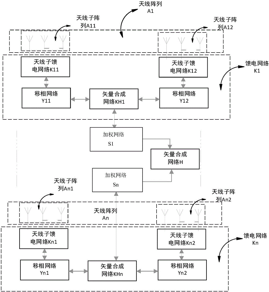
[0036] The antenna array is formed by feeding and spatially arranging two or more single antennas working at the same frequency according to certain requirements. The antenna array in the present invention includes two antenna sub-arrays, and the antenna sub-arrays Same as the definition of the antenna array, each antenna sub-array contains two or more single antennas of the same frequency, the single antenna is the antenna unit, and each antenna unit can be uniformly distributed in the horizontal direction into a linear array, or can be arranged on a plane distributed in an ar...


PUM


Abstract

The invention relates to an array antenna wave beam shaping system and a wave beam scanning method thereof. The system comprises at least two antenna arrays, each antenna array comprises two antenna subarrays in anti-phase coupling, signals of the antenna arrays are weighted, vector composition is carried out on the weighted signals, and an antenna wave beam is obtained. The signal weighted values of the antenna arrays are changed to realize antenna wave beam scanning.

Description

technical field [0001] The invention belongs to the technical field of wireless communication, and in particular relates to an array antenna beam forming system and a beam scanning method thereof. Background technique [0002] In modern wireless communication systems, the antenna plays an indispensable role. The antenna is responsible for converting the electrical signal in the circuit into a wireless signal and transmitting it into the air, or converting the wireless signal received from the air into an electrical signal. It can be seen that the performance of the antenna directly affects the performance of the entire communication system. How to improve the performance of the system by improving the performance of the antenna has always been a hot spot of research at home and abroad. Beamforming technology is a technology that processes signals from multiple antennas through digital signal processing methods to obtain desired waveforms. Through the beamforming technology,...

Claims


Application Information

Patent Timeline
Patent Type & Authority Applications(China)
IPC IPC(8): H01Q21/00H01Q3/34H01Q3/28
CPCH01Q3/28H01Q3/34H01Q21/00H01Q21/0006
Inventor 朱毛毛
Owner 无锡费舍太格科技有限公司
Why Eureka
Try Eureka