Micro-strip printed ultra-wideband log periodic antenna and antenna array

A logarithmic periodic antenna and ultra-wideband technology, applied in the field of antennas, can solve problems such as the feeding problem of several periodic antennas, achieve the effect of expanding the frequency range, expanding the workable frequency range, and reducing the impact

Inactive Publication Date: 2019-07-16
CHINA ELECTRONIC TECH GRP CORP NO 38 RES INST
View PDF4 Cites 0 Cited by
  • Summary
  • Abstract
  • Description
  • Claims
  • Application Information

AI Technical Summary

Problems solved by technology

[0006] The technical problem to be solved by the present invention is: how to solve the feeding problem of the logarithmic periodic antenna at a higher frequency
[0008] The invention feeds the logarithmic period radiation antenna through the feeder layer microstrip plate, so that the feeding point is at the near-ground end of the logarithmic period, and solves the problem of feeding the microstrip printed ultra-wideband logarithmic period antenna at a higher fr

Method used


Image

  • Micro-strip printed ultra-wideband log periodic antenna and antenna array
  • Micro-strip printed ultra-wideband log periodic antenna and antenna array
  • Micro-strip printed ultra-wideband log periodic antenna and antenna array

Examples


Example Embodiment

[0029] Example one:

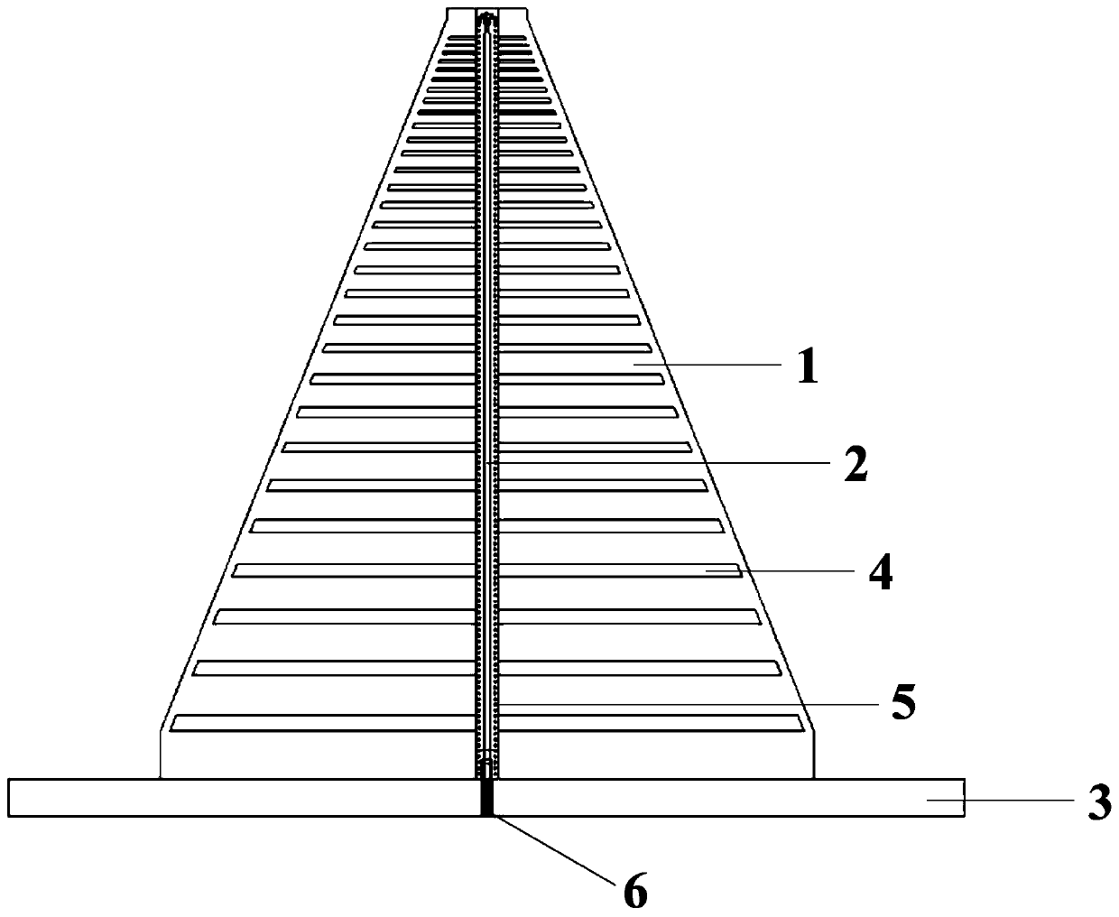
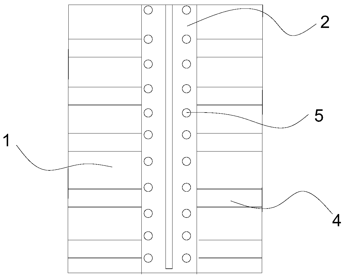
[0030] Such as figure 1 As shown, this embodiment discloses a microstrip printed ultra-wideband log periodic antenna, including an antenna layer microstrip board 1, a feeder layer microstrip board 2, a metal reflector 3, and a radio frequency connector 6; the upper two sides of the antenna layer microstrip board 1 Equipped with a logarithmic period antenna 4, the antenna layer microstrip board 1 is vertically mounted on the metal reflector 3, the feeder layer microstrip board 2 is glued to the front side of the antenna layer microstrip board 1, the logarithmic period antenna 4 and the feeder layer The microstrip board 2 is installed on the same side, and the feeder layer microstrip board is electrically connected to the log periodic antenna. The radio frequency connector 6 is connected to the middle layer patch of the feeder layer microstrip board 2 after passing through the metal reflector 3, and the feed point is at the near ground end.

[0031] Such as fi...

Example Embodiment

[0036] Embodiment two:

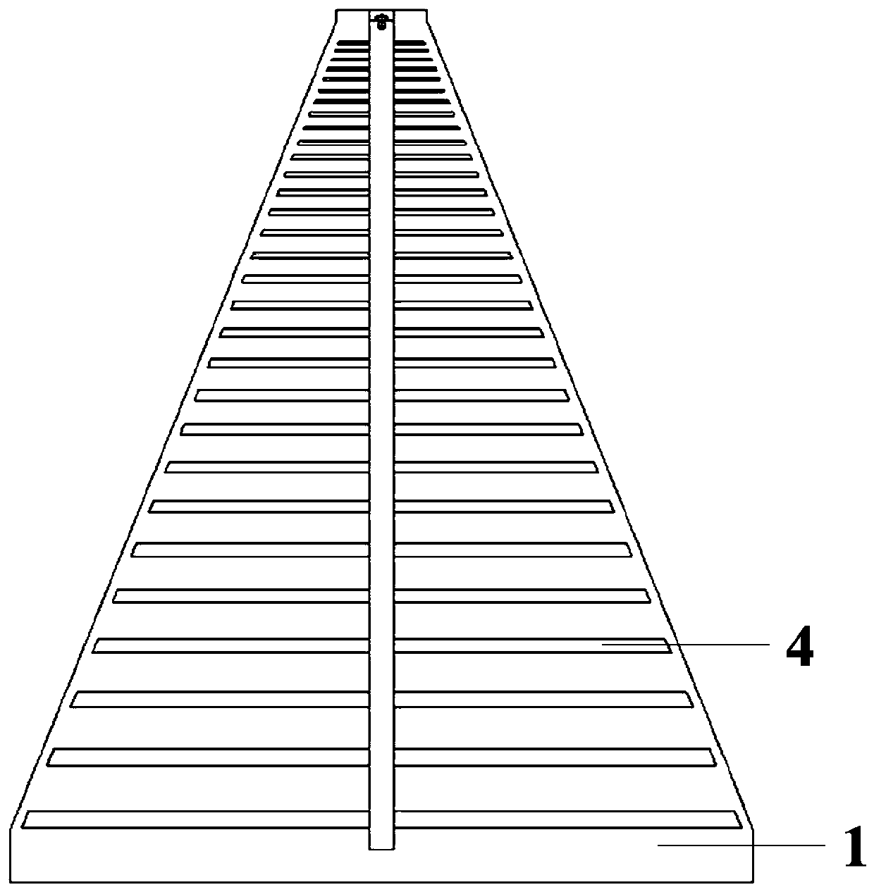
[0037] Such as image 3 As shown, the difference between this embodiment and the first embodiment is that: in the first embodiment, a feeder layer microstrip board 2 is provided in the front, and there is no balance body in the back; and in this embodiment, in order to make the antenna more stable, there are The balance body that balances the entire structure.

[0038] The balance body in this embodiment is the feeder layer microstrip board 2. The feeding layer microstrip plate 2 on the rear side is a symmetrical structure placed for balance, and is not electrically connected to the log-period radiating antenna 4 and the metal reflector 3, and of course, it can also be another balance body.

[0039] Such as Figure 4 As shown, the present invention also provides an antenna array including a number of the microstrip printed ultra-wideband log periodic antennas, and the microstrip printed ultra-wideband log periodic antennas in the first embodiment or / and the...


PUM


Abstract

The invention discloses a micro-strip printed ultra-wideband log periodic antenna. The antenna comprises an antenna layer micro-strip plate, a feeder line layer micro-strip plate, a metal reflection plate and a radio frequency connector; a log periodic antenna is printed on the antenna layer micro-strip plate; the antenna layer micro-strip plate is vertically mounted on the metal reflection plate;the feeder line layer micro-strip plate is adhered to one side of the antenna layer micro-strip plate; the log periodic antenna and the feeder line layer micro-strip plate are mounted on the same side; the feeder line layer micro-strip plate is in feed connection with the log periodic antenna; the radio frequency connector is connected with the bottom end of the feeder line layer micro-strip plate; and a feed point is arranged at a near-ground end. The invention further discloses an antenna array. The micro-strip printed ultra-wideband log periodic antenna has the beneficial effects that thefeed point is arranged at the near-ground end of the log periodic antenna, so that the feed problem of the micro-strip printed ultra-wideband log periodic antenna during working at a relatively high frequency is solved; traditional far-ground end feed is converted into near-ground end feed, so that the influence of feeder lines on the log periodic antenna is reduced as much as possible; and the micro-strip printed ultra-wideband log periodic antenna has relatively good electrical performance and radiation performance.

Description

technical field [0001] The invention relates to an antenna, in particular to a microstrip printed ultra-wideband logarithmic periodic antenna. Background technique [0002] With the development of radar technology, radar systems have higher and higher requirements on the performance of antennas, and the advantages of ultra-wideband antennas are highlighted. [0003] As a broadband antenna with excellent electrical characteristics, the logarithmic periodic antenna has a simple structure and is easy to process, and has stable radiation characteristics and high directivity in a wide frequency range. Communication, direction finding, search, electronic countermeasures and other aspects have been widely used. [0004] The feeding method of the traditional logarithmic periodic antenna is generally to use the coaxial line to feed, and the coaxial line is welded to the remote end of the antenna. In other words, the influence of the coaxial line cannot be ignored, and the welding a...

Claims


Application Information

Patent Timeline
IPC IPC(8): H01Q1/38H01Q1/50H01Q15/14H01Q19/10H01Q21/00
CPCH01Q1/38H01Q1/50H01Q15/14H01Q19/10H01Q21/0006H01Q21/0075
Inventor 王亚茹张小林苗菁张琪春王杰金谋平
Owner CHINA ELECTRONIC TECH GRP CORP NO 38 RES INST
Why Eureka
Try Eureka