Loudspeaker diaphragm and loudspeaker using the same

a technology of loudspeaker and diaphragm, which is applied in the direction of transducer diaphragm, transducer details, instruments, etc., can solve the problems of the loudspeaker, and insufficient rigidity of the conventional loudspeaker diaphragm, etc., to suppress the overall height of the loudspeaker diaphragm, increase the rigidity of the dome portion

Inactive Publication Date: 2009-03-05
ONKYO KK
View PDF6 Cites 27 Cited by
  • Summary
  • Abstract
  • Description
  • Claims
  • Application Information

AI Technical Summary

Benefits of technology

[0016]The dome portion includes the concave dome portion formed at the center thereof, the convex dome portion along the outer periphery of the concave dome portion, and the voice coil attachment portion along the outer periphery of the convex dome portion. Thus, the dome portion includes the convex dome portion having a sufficient rigidity as a loudspeaker diaphragm, and the voice coil attachment portion provided along the outer periphery of the convex dome portion as a flat portion to which the voice coil is attached, wherein the area around the top of the convex dome portion, which most protrudes to thereby define the overall height of the loudspeaker diaphragm, is depressed to form the concave dome portion. Therefore, it is possible to suppress the overall height of the loudspeaker diaphragm to be low, while increasing the rigidity of the dome portion.
[0017]The dome portion of the loudspeaker diaphragm of the present invention includes the plurality of depressed ribs each extending in the radial direction across the boundary between the concave dome portion and the convex dome portion, and the plurality of protruding ribs extending in the radial direction across the boundary between the convex dome portion and the voice coil attachment portion. A “depressed rib” as used herein refers to a groove extending in the radial direction while being depressed in the rearward direction as viewed from the front side of the loudspeaker diaphragm. A “protruding rib” as used herein refers to a ridge extending in the radial direction while protruding in the frontward direction, as opposed to a depressed rib. When viewed from the rear side, however, a protruding rib is also a groove, as is a depressed rib, extending in the radial direction while being depressed in the frontward direction. The depressed ribs and the protruding ribs are both formed to extend in the radial direction from the center of the loudspeaker diaphragm for the purpose of increasing the rigidity of the dome portion in the ribbed area.
[0018]The plurality of depressed ribs are formed to extend in the radial direction across the boundary between the concave dome portion and the convex dome portion, thus reinforcing the boundary portion between the concave dome portion and the convex dome portion. The plurality of protruding ribs are formed to extend in the radial direction across the boundary between the convex dome portion and the voice coil attachment portion, thus reinforcing the boundary portion between the convex dome portion and the voice coil attachment portion. Each protruding rib is spaced apart in the circumferential direction from two adjacent depressed ribs. Preferably, in the convex dome portion of the dome portion, the depressed ribs and the protruding ribs alternate with each other in the circumferential direction. Thus, not only is the overall rigidity of the convex dome portion reinforced, but also the boundary portion between the convex dome portion and the concave dome portion and the boundary portion between the convex dome portion and the voice coil attachment portion are reinforced. Thus, even though the loudspeaker diaphragm includes the concave dome portion in order to reduce the overall height dimension of the loudspeaker diaphragm, it is possible to suppress divided vibrations of the dome portion of the loudspeaker diaphragm and prevent a dip from occurring in the high range of the frequency response.
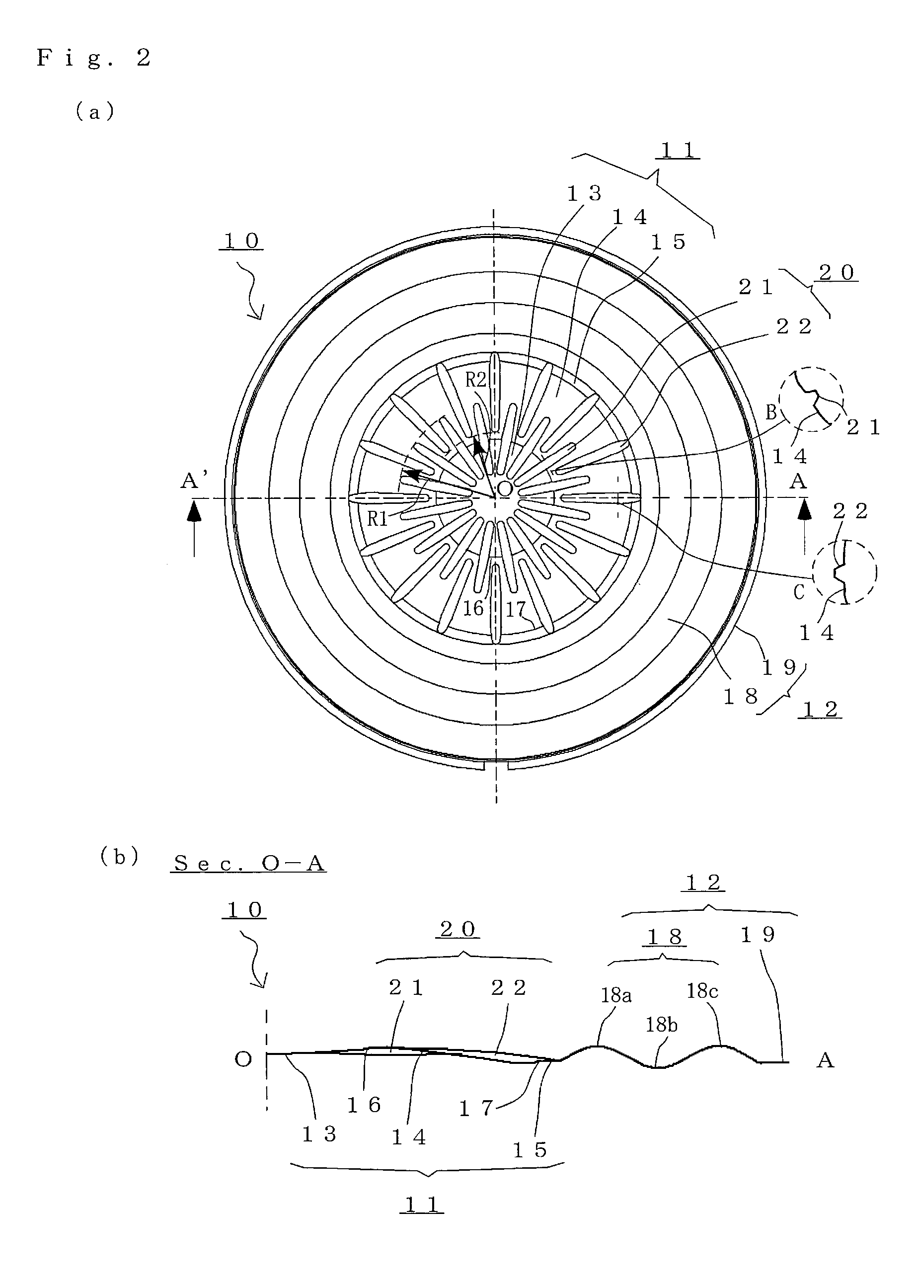
[0019]Where the first radius value defining the distal end of the depressed ribs is greater than the second radius value defining the proximal end of the protruding ribs, the protruding ribs and the depressed ribs will alternate with each other in the circumferential direction across the convex dome portion at a predetermined distance from the center. Thus, there is provided a reinforcement structure in which the protruding ribs and the depressed ribs overlap with each other around the radially middle portion of the convex dome portion, which is the primary portion of the loudspeaker diaphragm, whereby the rigidity of the dome portion of the loudspeaker diaphragm can be increased in a well-balanced manner. As a result, it is possible to realize a loudspeaker diaphragm capable of a stable operation and a desirable sound reproduction, and to realize a loudspeaker using the same.
[0020]The shape of the corrugated edge portion may be any suitable shape as long as it appropriately allows vibrations of the dome portion of the loudspeaker diaphragm and the voice coil, and may be a corrugated shape, a rolled shape, or a conical shape. With the rigidity of the dome portion being increased by ribs extending across the boundary portion, a loudspeaker using the loudspeaker diaphragm of the present invention has a wide reproduction frequency range and is less likely to have problems such as noise even when an input signal of a large amplitude is applied to the voice coil, thereby realizing a desirable sound reproduction.

Problems solved by technology

However, the conventional loudspeaker diaphragms and loudspeakers may not be sufficient for realizing both a further reduction in the thickness of a loudspeaker suitable for a portable electronic device and a countermeasure against peaks and dips in the frequency response over the high range.
For example, when a concave dome-shaped depression is formed in a portion of a generally dome-like shape in order to reduce the overall height dimension of a loudspeaker diaphragm, the boundary between the concave dome-shaped depression and the convex dome-shaped portion acts as a node of a vibration mode to prevent a stable operation, wherein dips occur in the frequency response over the high range, thus failing to realize a desirable sound reproduction.

Method used


Image

  • Loudspeaker diaphragm and loudspeaker using the same
  • Loudspeaker diaphragm and loudspeaker using the same
  • Loudspeaker diaphragm and loudspeaker using the same

Examples


embodiment 1

[0026]FIGS. 1A and 1B illustrate a loudspeaker 1 using a loudspeaker diaphragm 10 in a preferred embodiment of the present invention. FIG. 1A is a plan view of the loudspeaker 1, and FIG. 1B is a side cross-sectional view thereof taken along line A-A′. The loudspeaker 1 of the present embodiment is a small and thin electrodynamic loudspeaker having a diameter of 20 mm, and includes a light-weighted magnetic circuit 2 of an inner-magnet type, and the loudspeaker diaphragm 10. The loudspeaker diaphragm 10 is obtained by molding a PEI (polyetherimide) resin film member, and is a single-piece member including a dome portion 11 and an edge portion 12.

[0027]In addition to the magnetic circuit 2 formed by a pole, a magnet and a yoke and defining a magnetic gap 3 therein, the loudspeaker 1 also includes a frame 4 attached to the magnetic circuit 2 for supporting the loudspeaker diaphragm 10 so as to allow vibrations of the loudspeaker diaphragm 10, and a voice coil 5 attached to the rear su...


PUM


Abstract

A loudspeaker diaphragm having a small overall height dimension, in which a dome portion has a sufficient rigidity and which is capable of realizing a stable loudspeaker operation, wherein the loudspeaker diaphragm can realize a desirable sound reproduction without noise, or the like, with a frequency response that is flat over a wide range. In the loudspeaker diaphragm of the present invention, the dome portion includes a concave dome portion formed at a center thereof, a convex dome portion along an outer periphery of the concave dome portion, a plurality of depressed ribs each extending in a radial direction across a boundary between the concave dome portion and the convex dome portion, a voice coil attachment portion along an outer periphery of the convex dome portion, and a plurality of protruding ribs extending in the radial direction across a boundary between the convex dome portion and the voice coil attachment portion, wherein each protruding rib is spaced apart in a circumferential direction from two adjacent depressed ribs.

Description

BACKGROUND OF THE INVENTION[0001]1. Field of the Invention[0002]The present invention relates to a loudspeaker diaphragm for use in a loudspeaker for reproducing sound in a portable electronic device such as a portable telephone or a portable game device, and a loudspeaker using such a loudspeaker diaphragm.[0003]2. Description of the Related Art[0004]Some small loudspeakers employ a loudspeaker diaphragm being a film member of a resin such as PEI (polyetherimide), wherein the film member is a single-piece member including a dome portion and an edge portion, the edge portion extending along the outer periphery of the dome portion. Where such a loudspeaker is an electrodynamic loudspeaker, a voice coil to which an audio signal current is supplied may be attached to the junction between the dome portion and the edge portion of the loudspeaker diaphragm on the rear surface of the loudspeaker diaphragm. The outer periphery of the edge portion of the loudspeaker diaphragm is fixed to a f...

Claims


Application Information

Patent Timeline
Patent Type & Authority Applications(United States)
IPC IPC(8): H04R9/06H04R7/02H04R1/00H04R11/02
CPCH04R7/02
Inventor MAEDA, TATSUYA
Owner ONKYO KK
Why Eureka
Try Eureka