Optical fiber cable suited for blown installation or pushing installation in microducts of small diameter

a micro-duct and optical fiber technology, applied in the field of optical fiber cables, can solve the problems of cable, however, not being regarded as a micro-cable, and duct installation, however, using space inefficiently, and achieves the effects of reducing post-extrusion shrinkage, reducing friction, and sufficient stiffness

Inactive Publication Date: 2009-08-04
DRAKA COMTEQ BV
View PDF13 Cites 148 Cited by
  • Summary
  • Abstract
  • Description
  • Claims
  • Application Information

AI Technical Summary

Benefits of technology

[0017]Another object of the present invention is to develop a jacket material for a microcable that provides low friction and sufficient stiffness, as well as limited post-extrusion shrinkage. The cable facilitates high fiber count and blowing performance, and is mechanically robust enough to be safely installed in an outside plant environment.

Problems solved by technology

Traditional duct installation, however, uses space inefficiently.
Such a cable, however, is not regarded as a microcable.

Method used


Image

  • Optical fiber cable suited for blown installation or pushing installation in microducts of small diameter
  • Optical fiber cable suited for blown installation or pushing installation in microducts of small diameter

Examples


Embodiment Construction

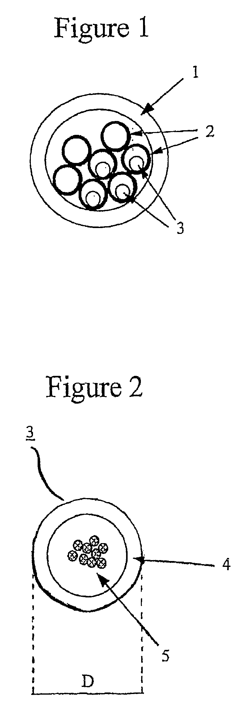
[0022]An exemplary embodiment of the present invention is explained with reference to FIGS. 1 and 2.

[0023]FIG. 1 shows an example of microcabling technology for the deployment of optical fiber cables. This configuration depicts a duct 1 in which seven microducts 2 have been placed. As depicted, four of the seven microducts 2 have a microcable 3 inside.

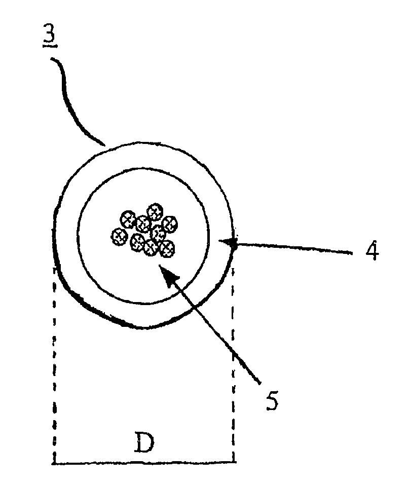
[0024]FIG. 2 shows a microcable 3 according to the present invention. It includes a single buffer tube 4 holding a plurality of optical fibers 5. The fibers do not have a fixed position within buffer tube 4, nor to each other. The buffer tube 4 functions as an outer sheath, which is typically smooth and free of recesses. A water-repelling gel (e.g., a thixotropic material) typically surrounds the optical fibers 5 within the buffer tube 4.

[0025]The buffer tube 4 of the microcable 3 is typically a homogeneous structure made of single polymeric material, more typically a thermoplastic material such as polyamide (i.e., nylon), polycarbonat...


PUM


Abstract

The invention relates to optical fiber cables and, more specifically, to an optical fiber cable especially suited for blown installation or pushing installation in microducts of small diameter. An exemplary microcable for installation in small microducts has an outer sheath as buffer tube that holds a plurality of optical fibers without a layer of strength elements stranded around the outer sheath, which is made of one single thermoplastic material.

Description

CROSS-REFERENCE TO PRIORITY APPLICATIONS[0001]This application hereby claims the benefit of pending Dutch Application No. 1,031,110 (filed Feb. 8, 2006 at the Dutch Patent Office) and pending International Application No. PCT / NL2006 / 000289 (filed Jun. 13, 2006 at the Dutch Patent Office). International Application No. PCT / NL2006 / 000289 designates the United States and, accordingly, this application is a continuation-in-part thereof.[0002]Dutch Application No. 1,031,110 and International Application No. PCT / NL2006 / 000289 (i.e., the priority applications) were each filed in the name of Draka Comteq B.V., and each is hereby incorporated by reference in its entirety.FIELD OF THE INVENTION[0003]The invention relates to optical fiber cables and, more specifically, to an optical fiber cable especially suited for blown installation or pushing installation in microducts of small diameter.BACKGROUND OF THE INVENTION[0004]Fiber optic cables have been commonly deployed by installing them in duc...

Claims


Application Information

Patent Timeline
Patent Type & Authority Patents(United States)
IPC IPC(8): G02B6/44
CPCG02B6/4438
Inventor NOTHOFER, KLAUSWEISS, ALEXANDERLAUSCH, PETER
Owner DRAKA COMTEQ BV
Why Eureka
Try Eureka