RF generator with phase controlled mosfets

a phase control, mosfet technology, applied in the direction of electric variable regulation, process and machine control, instruments, etc., can solve the problems of linear amplification, loss of class-d devices, power loss proportional and direct frequency increase,

Active Publication Date: 2005-12-08
LITTELFUSE INC
View PDF20 Cites 28 Cited by
  • Summary
  • Abstract
  • Description
  • Claims
  • Application Information

AI Technical Summary

Benefits of technology

[0017] There are various advantages in operating the RF generator using the phase shift technique: (1) may be operated in a broader frequency range, (2) may operate with fixed DC voltages that are not highly filtered, (3) eliminates the need for a variable DC power supply, and (4) may be operated at very low power to full power.

Problems solved by technology

This results in linear amplification.
Generally, class-D devices suffer from losses due to saturation, switching speed, and drain capacitance.
Drain capacitances are charged and discharged generally once per RF cycle, which can result in power loss that is proportional and increases directly with frequency.
Variations in load impedance and shunt susceptance cause the power amplifier to deviate from optimum operation, but the degradations in performance are generally no worse than those for classes A and B.
Efficiency is high but power control is difficult.
Power control is usually a variable DC power supply which results in slow control of the output power and difficulty in controlling power at low levels.
It is possible to drive these classes with a sine wave; however, the turn-on threshold varies with the MOSFET die temperature which will change the conduction angle (pulse width) of the MOSFET, which can be problematic.

Method used


Image

  • RF generator with phase controlled mosfets
  • RF generator with phase controlled mosfets
  • RF generator with phase controlled mosfets

Examples


Embodiment Construction

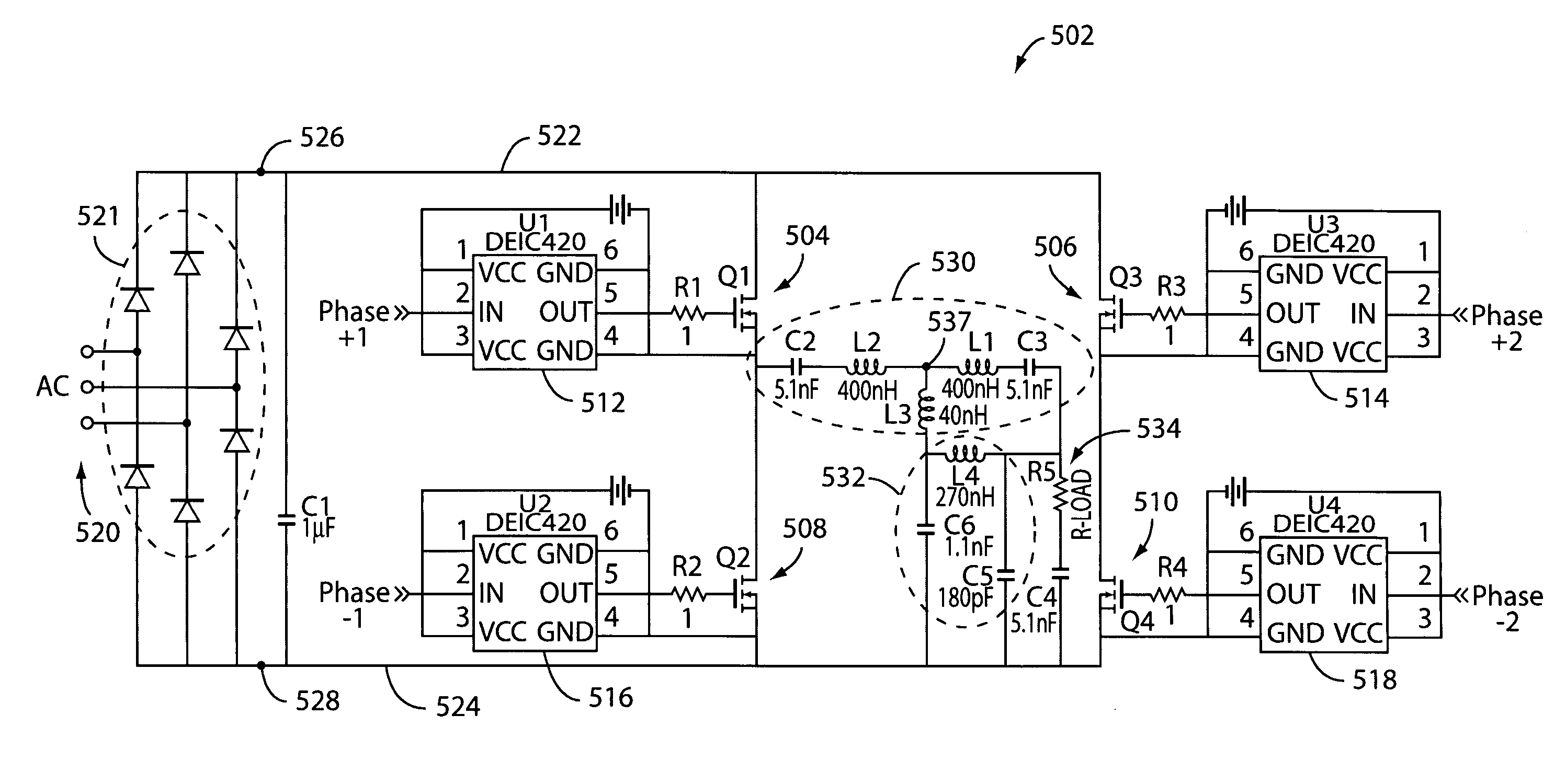
[0036] The present invention relates to an RF generator that has a full bridge configuration. The full bridge configuration comprises high voltage MOSFETs that are operated using phase shift techniques.

[0037] The present embodiment relates to an RF generator operating at an ISM frequency, e.g., 13.56 MHz, as disclosed in U.S. patent application Ser. No. ______, entitled, “RF Generator With Reduced Size and Weight,” filed on May 27, 2005, and U.S. patent application Ser. No. ______, entitled, “RF Generator With Commutation Inductor,” filed on May 27, 2005, which are both assigned to the assignee of the present application, and which are both incorporated by reference.

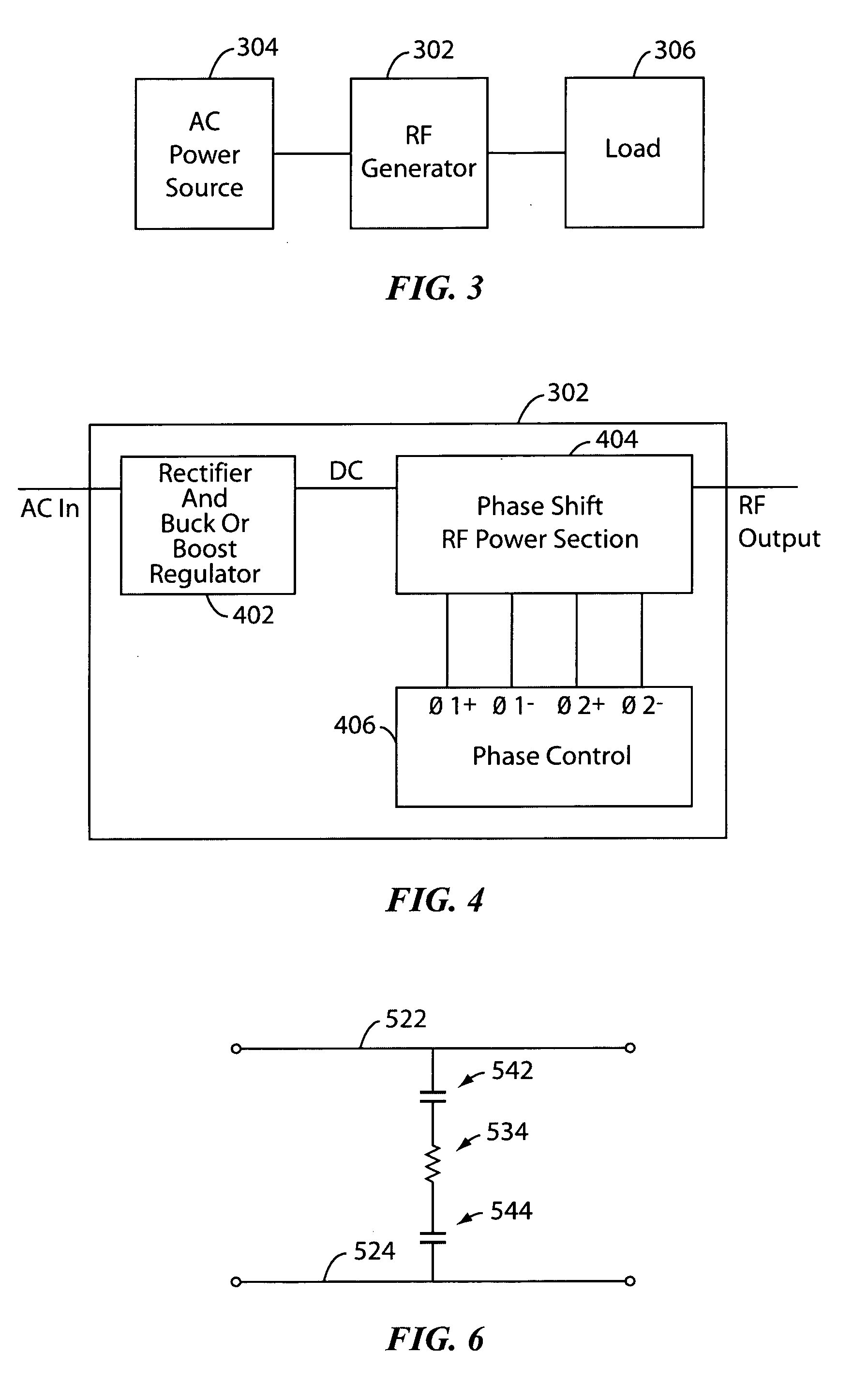
[0038] The RF generator uses a high voltage phase shift controlled full bridge. A full bridge design offers several advantages which are helpful in RF operation. These include a higher utilization of the MOSFET ratings. In a bridge design, the voltage is limited to the supply rail (e.g., positive rail), whereas it is n...


PUM


Abstract

A radio frequency (RF) generator comprises a first half bridge including first and second power transistors; a second half bridge including first and second power transistors; an output node coupling the first and second half bridges and RF signals to a load; positive and negative rails coupled to an AC power source via rectifier; a first blocking capacitor provided between the positive rail and the load; and a second blocking capacitor provided between the negative rail and the load. The first and second blocking capacitors are configured to isolate the load from the AC power source.

Description

BACKGROUND OF THE INVENTION [0001] The present applications claims the benefit of U.S. Provisional Patent Application No. 60 / 575,435, filed on May 28, 2004, which is incorporated by reference.BACKGROUND OF THE INVENTION [0002] The present invention relates to an radio frequency (RF) generator. [0003] A power amplifier or generator is a circuit for converting DC-input power into a significant amount of RF / microwave output power. There is a great variety of different power amplifiers (PAs). A transmitter contains one or more PAs, as well as ancillary circuits such as signal generators, frequency converters, modulators, signal processors, linearizers, and power supplies. As used herein, the terms “power generator,”“RF generator,” and “power amplifier” are used interchangeably. [0004] Frequencies from very low frequency (VLF) through millimeter wave (MMW) are used for communication, navigation, and broadcasting. Output powers vary from 10 mW in short-range unlicensed wireless systems to...

Claims


Application Information

Patent Timeline
Patent Type & Authority Applications(United States)
IPC IPC(8): H01L23/46H01L23/473H02M3/335H02M7/5387H03F1/30H03F1/52H03F3/19H03F3/193H03F3/217H03F3/24H05H1/36H05H1/46H05K7/20
CPCH01L23/473H01L2924/3011H02M7/5387H05K7/20927H01L2924/0002H01L2924/00
Inventor COLEMAN, CHARLES
Owner LITTELFUSE INC
Why Eureka
Try Eureka