Voltage control oscillator and voltage control oscillator unit

Inactive Publication Date: 2007-04-05
SHARP KK
View PDF1 Cites 30 Cited by
  • Summary
  • Abstract
  • Description
  • Claims
  • Application Information

AI Technical Summary

Benefits of technology

[0015] The present invention is in view of the above problems, and has as an object to provide a voltage control oscillator a

Problems solved by technology

In the case where a voltage control oscillator (the voltage control oscillator may also be referred to as a “VCO” hereinafter) that oscillates in such a wide band frequency range necessary for broadcast receiving is installed on an integrated circuit, it is not possible with one VCO to provide

Method used


Image

  • Voltage control oscillator and voltage control oscillator unit
  • Voltage control oscillator and voltage control oscillator unit
  • Voltage control oscillator and voltage control oscillator unit

Examples


embodiment 1

(Embodiment 1)

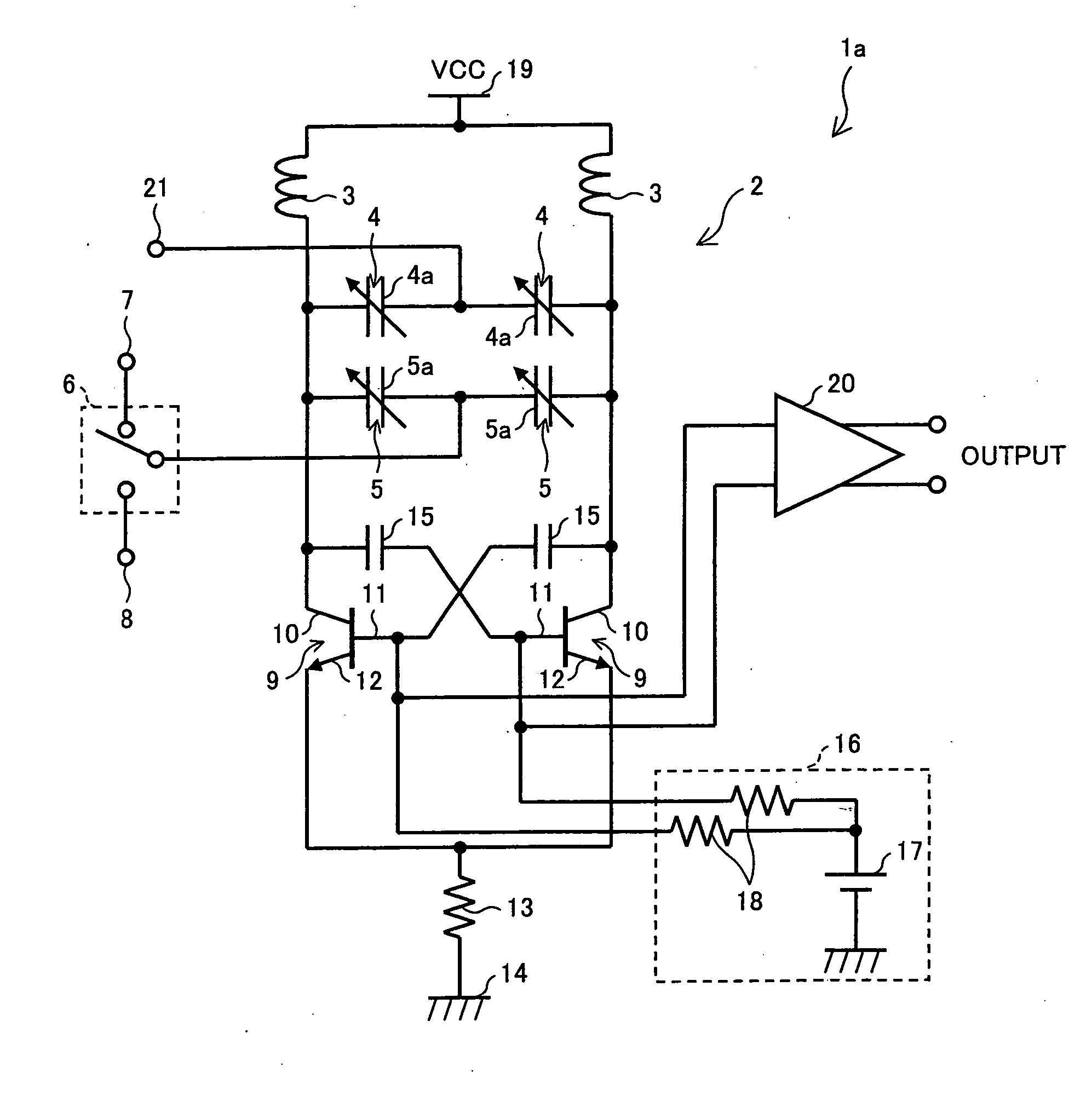
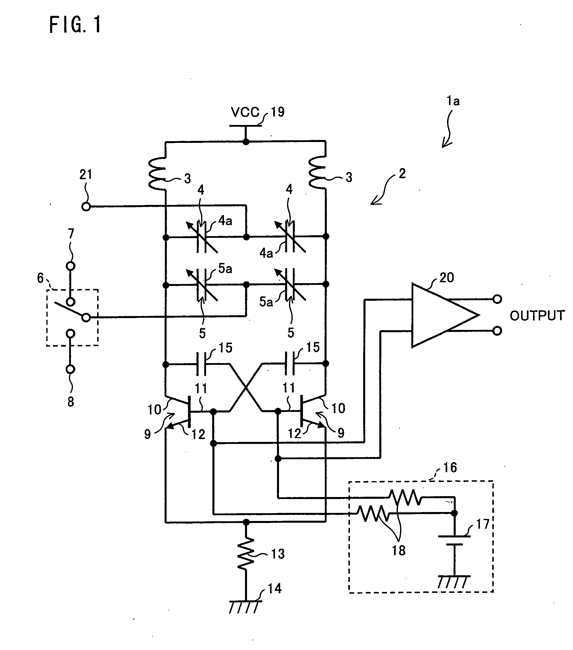
[0033]FIG. 1 is a circuit diagram illustrating a configuration of a voltage control oscillator la, according to Embodiment 1 of the present invention. The VCO 1a includes two inductors 3 that are connected, parallel to each other, to a power-supply voltage terminal 19. On the opposite side of the power-supply voltage terminal 19, the inductors 3 are respectively connected to variable capacitors 4 power-supply voltage terminal. The variable capacitors 4 have capacitance controlling terminals 4a, respectively, that are connected to a frequency control voltage input terminal 21 on the opposite side of the inductors 3.

[0034] Further, on the side of the inductors 3 opposite the power-supply voltage terminal 19, the variable capacitors 4 are connected to variable capacitors 5, respectively. The variable capacitors 5 have capacitance controlling terminals 5a, respectively, that are connected to a switch 6 on the opposite side of the inductors 3. The switch 6 selectively conn...

embodiment 2

(Embodiment 2)

[0047]FIG. 3 is a circuit diagram illustrating a configuration of a voltage control oscillator b of Embodiment 2. Components that are the same as the components described above are given the same reference numerals, and detail description thereof is omitted. The same applies to the later shown Figures.

[0048] The voltage control oscillator 1b includes MOS-type variable capacitors 37 and 38 in place of the variable capacitors 4 and 5. The greater the variable capacitance ratio of the variable capacitor is, the greater the oscillation-frequency variable-ratio (ratio of oscillation frequency variable width to center frequency) of the VCO 1b will be. The variable capacitance ratio of the variable capacitors is decided by a device that can be used in a process. In the embodiments of the present invention, the VCO gain Kv is suppressed by using variable capacitors whose capacitances are partially fixed. Therefore, the present invention is especially effective if variable cap...

embodiment 3

(Embodiment 3)

[0049]FIG. 4 is a circuit diagram illustrating a configuration of a voltage control oscillator 1c of Embodiment 3. The switch 6 selectively connects the capacitance controlling terminal 5a to any one of (i) a power-supply voltage terminal 39 to which the power-supply voltage VCC is supplied and (ii) a ground 40.

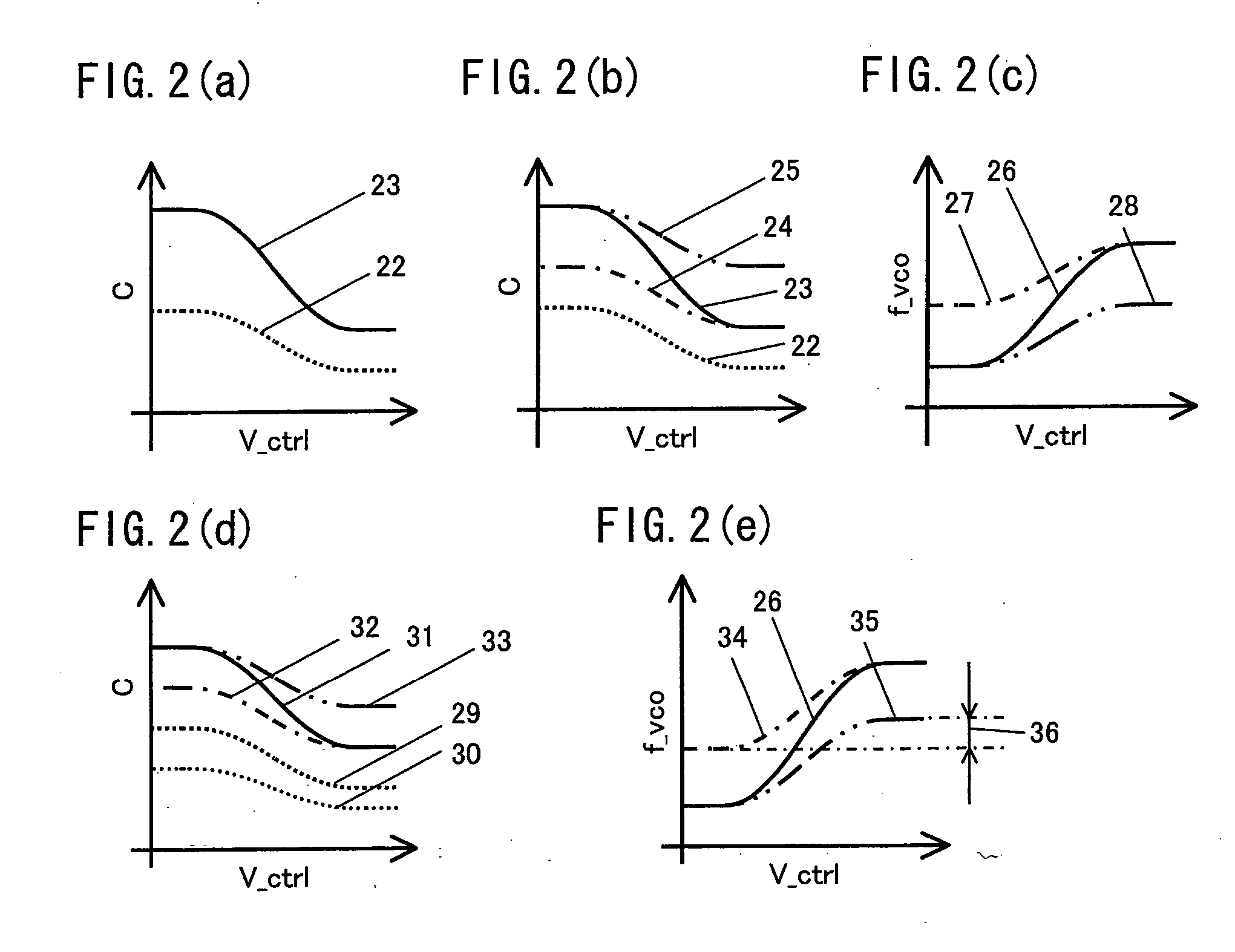
[0050] In the case where the C-V characteristics of the variable capacitors in FIG. 2(a) takes (i) a maximum capacitance if the frequency control voltage is 0V and (ii) a minimum capacitance if the frequency control voltage is the power-supply voltage, the capacitance controlling terminals 5a of the variable capacitors 5 are connected to any one of (i) the power-supply voltage terminal 39 and (ii) the ground 40 by the switch 6 such that the switch 6 switches the power-supply voltage terminal 39 and the ground 40, as illustrated in FIG. 4. This makes it possible to realize (i) the f-V characteristics of the curves 27 and 28 shown in FIG. 2(c) and (ii) the f-V ch...


PUM


Abstract

A voltage control oscillator that is provided to suitably receive digital broadcasting and is produced at low costs includes: a resonance circuit that includes variable capacitors, each having a capacitance controlling terminal, that are provided parallel to each other and are connected to an inductor, the circuit resonating at a resonant frequency that varies depending upon a sum of (i) an inductance of the inductor and (ii) capacitances of the variable capacitors; and at least one switch to determine what should be connected to at least one of said capacitance controlling terminals.

Description

[0001] This Nonprovisional application claims priority under 35 U.S.C. § 119(a) on Patent Application No. 289424 / 2005 filed in Japan on Sep. 30, 2005, the entire contents of which are hereby incorporated by reference.FIELD OF THE INVENTION [0002] The present invention relates to a voltage control oscillator and a voltage control oscillator unit that include a resonance circuit which includes at least two variable capacitors that are provided parallel to each other and are connected to an inductor, which resonance circuit resonates at a resonant frequency that varies depending upon a sum of an inductance of the inductor and capacitances of the variable capacitors. BACKGROUND OF THE INVENTION [0003] Generally, there is a demand for a broadcasting-receiving tuner to have a wide frequency range. For example, a satellite broadcasting-receiving tuner has a source frequency of 950 MHz to 2150 MHz, and a direct-conversion type tuner needs to include a local oscillator that oscillates at a f...

Claims


Application Information

Patent Timeline
IPC IPC(8): H03B5/08
CPCH03B5/1231H03B5/1212H03B5/1265H03B5/1253
Inventor AMANO, SHINJI
Owner SHARP KK
Why Eureka
Try Eureka