Eureka AIR delivers breakthrough ideas for toughest innovation challenges, trusted by R&D personnel around the world.

Length-adjustable work platform for power field

A working platform and electric power technology, applied in the direction of overhead lines/cable equipment, buildings, ladders, etc., can solve the problems of high labor intensity and poor convenience for operators, and achieve the effects of simplified and convenient operation steps, safe construction, and avoiding sliding

Inactive Publication Date: 2016-12-21
SICHUAN XINGZHI ZHIHUI INTPROP OPERATION CO LTD
View PDF7 Cites 0 Cited by
  • Summary
  • Abstract
  • Description
  • Claims
  • Application Information

AI Technical Summary

Problems solved by technology

[0002] Since the widespread development of 0KV live-line work, the main method is the intermediate potential operation method, using insulated steep-wall vehicles to carry out operations. However, in places such as mountainous fields, insulated bucket-wall vehicles cannot reach, which is less convenient and labor-intensive for operators.

Method used


Image

  • Length-adjustable work platform for power field

Examples


Embodiment 1

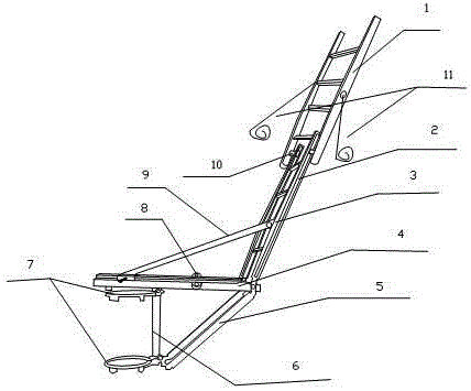
[0018] Such as figure 1 As shown, the present invention includes a first square ladder 1, a second square ladder 3, an insulating diagonal support rod 5, two hoops 7, a connecting rod 6, an insulating mounting platform 4 and an insulating diagonal stay rod 9. The second square One end of the ladder 3, the insulating installation platform 4 and the insulating diagonal support rod 5 is movably connected together, and the insulating installation platform 4 is located between the second square ladder 3 and the insulating diagonal support rod 5; The hoop 7 is also connected to the bottom of the insulating diagonal support rod 5 and the insulating installation platform 4 at both ends of the connecting rod 6; and can slide back and forth on the insulating installation platform 4; both sides of the second square ladder 3 are provided with chute 2, and two rollers 10 are arranged at the bottom of the first square ladder 1, and the two rollers 10 are respectively located on the first si...

Embodiment 2

[0021] In this embodiment, on the basis of Embodiment 1, the following technical enhancements are added: steel ropes 11 are respectively arranged on both sides of the first square ladder 1 . Both sides of the insulating mounting table 4 are respectively provided with sleeve holes 8 . When the first square ladder is lifted to the required height, pull the steel ropes located on both sides of the first square ladder to the sleeve holes to fix it, so as to increase the stability of the first square ladder, and the operator stands on the first square ladder It is safer and will not affect the sliding of the insulating diagonal stay rod on the insulating installation platform.

Embodiment 3

[0023] The preferred specific structure of this embodiment is as follows on the basis of the above-mentioned embodiments: bolts are also arranged between the sliding end of the insulating diagonal stay rod 9 and the insulating mounting platform. When the insulation-free diagonal stay rod slides, the position of the second square ladder is also fixed, and the operator can realize the operation by standing on the square ladder, making the construction safer.

[0024] The insulating diagonal support rod 5 can rotate around the common end of the insulating diagonal support rod 5 and the connecting rod 6 .

[0025] The insulating diagonal support bar 5, the connecting bar 6 and the insulating installation platform 4 form a triangle.


PUM


Abstract

The invention discloses a length-adjustable work platform for the power field. The length-adjustable work platform comprises a first square ladder, a second square ladder, an insulating oblique supporting rod, two holding hoops, a connecting rod, an insulating mounting stage and an insulating oblique pull rod; one end of the second square ladder, one end of the insulating mounting stage and one end of the insulating oblique supporting rod are movably connected together; the insulating mounting stage is located between the second square ladder and the insulating oblique supporting rod; two ends of the connecting rod are connected with one holding hoop respectively; the two ends of the connecting rod are also connected with the bottom of the insulating oblique supporting rod and the insulating mounting stage respectively; and one end of the insulating oblique pull rod is movably connected with the second square ladder, and the other end of the insulating oblique pull rod is installed on the insulating mounting stage and can slide backwards and forwards on the insulating mounting stage. With the above structure adopted, a worker does not need to adjust the holding hoops when the work platform is not required to be moved to a rather large position, and the worker can realize the lifting operation of the platform with standing on the work platform. The device of the invention is safe in operation and simple. Since the holding hoops are not required to be moved, so that operation steps can be simplified, and work efficiency can be improved.

Description

technical field [0001] The invention relates to the field of electric power construction, in particular to a length-adjustable working platform for the electric power field. Background technique [0002] Since the widespread development of 0KV live work, the intermediate potential operation method is mainly used, and the operation is carried out by using insulated steep-wall vehicles. However, in mountainous areas and fields, the insulated bucket wall vehicles cannot reach, the convenience is poor, and the labor intensity of the operators is high. As long as the working platform used today needs to be lifted and lowered, the operator needs to leave the workbench, and then change the longitudinal position by moving the position of the hoop on the pole. Once the hoop is moved, the entire device will move accordingly. , and after moving the position, it is necessary to re-tighten the hoop to avoid the hoop from slipping during use. The operation is cumbersome, time-consuming an...

Claims


Application Information

Patent Timeline
Patent Type & Authority Applications(China)
IPC IPC(8): H02G1/02E06C9/08E06C7/18
Inventor 贺昶明
Owner SICHUAN XINGZHI ZHIHUI INTPROP OPERATION CO LTD
Why Eureka
Eureka Blog
Learn More