

High-voltage-power-transmission-tower bird repelling device
A transmission tower and bird repelling technology, which is applied in the installation of cables, electrical components, overhead installation, etc., can solve the problems of insignificant bird repelling effect, intimidation and repelling of birds, and simple structure of the bird repellent, so as to achieve the effect of repelling birds. Clear, expand the range, enhance the effect of bird repelling effect
- Summary
- Abstract
- Description
- Claims
- Application Information
AI Technical Summary
Problems solved by technology
Method used
Image

Examples
no. 1 example
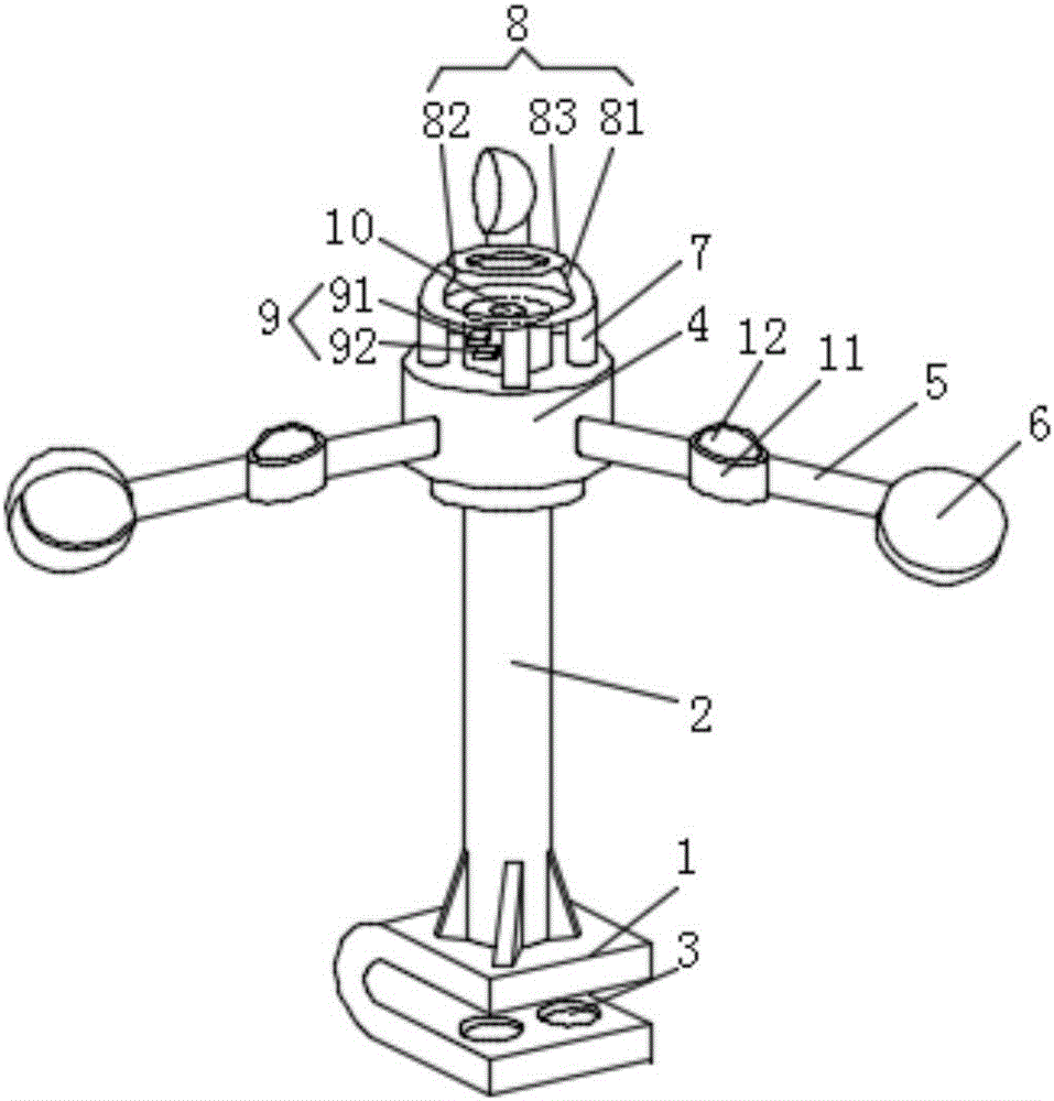
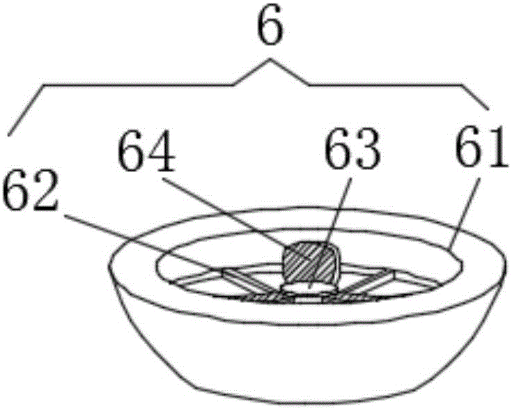
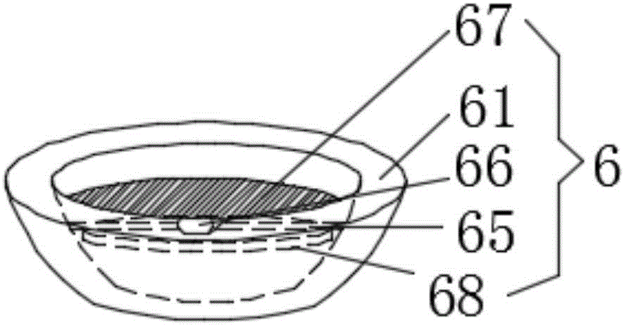
[0019] see figure 1 , figure 2 with Figure 4 , This patent provides the first embodiment: a high-voltage transmission tower bird repelling device, including a U-shaped base 1, a support rod 2 is vertically installed on the U-shaped base 1, and a mounting hole is provided in the middle of the U-shaped base 1 3. A rotating shaft 4 is installed on the top of the support rod 2, and a plurality of rotating arms 5 are fixedly installed on the side wall of the rotating shaft 4. The middle part of the rotating arm 5 is provided with an auxiliary wind bowl 11, and the auxiliary wind bowl 11 An auxiliary mirror 12 is rotatably installed in the inner cavity, and the head end of the rotating arm 5 is provided with a wind bowl 6. The number of the rotating arm 5 is at least three, and the rotating arm 5 takes the support rod 2 as the center of rotation. Symmetrically distributed, the rotating shaft 4 is fixedly installed with a reflection device 8 through the support feet 7 evenly inst...
no. 2 example
[0022] see figure 1 , image 3 with Figure 4 , this patent provides a second embodiment: a high-voltage transmission tower bird repelling device, including a U-shaped base 1, a support rod 2 is vertically installed on the U-shaped base 1, and a mounting hole is provided in the middle of the U-shaped base 1 3. A rotating shaft 4 is installed on the top of the support rod 2, and a plurality of rotating arms 5 are fixedly installed on the side wall of the rotating shaft 4. The middle part of the rotating arm 5 is provided with an auxiliary wind bowl 11, and the auxiliary wind bowl 11 An auxiliary mirror 12 is rotatably installed in the inner cavity, and the head end of the rotating arm 5 is provided with a wind bowl 6. The number of the rotating arm 5 is at least three, and the rotating arm 5 takes the support rod 2 as the center of rotation. Symmetrically distributed, the rotating shaft 4 is fixedly installed with a reflection device 8 through the support feet 7 evenly instal...
PUM
 Abstract
Description
Claims
Application Information