Eureka AIR delivers breakthrough ideas for toughest innovation challenges, trusted by R&D personnel around the world.

Quick release screw lock riveting tooling

A technology for riveting tooling and riveting tools, which is applied in metal processing, manufacturing tools, metal processing equipment, etc., and can solve problems such as springs that cannot be crimped in place, lock buckles that are not firmly riveted, and lock buckle springs that are too elastic

Active Publication Date: 2018-07-13
TIANJIN JINHANG COMP TECH RES INST
View PDF5 Cites 0 Cited by
  • Summary
  • Abstract
  • Description
  • Claims
  • Application Information

AI Technical Summary

Problems solved by technology

Due to the high elasticity of the lock spring, the disadvantages caused by manual pressing are as follows: First, it consumes manpower. Generally, the pressing personnel press 3-4 locks and have to replace them. Otherwise, the spring cannot be pressed into place due to exhaustion.
Secondly, riveting a lock buckle requires at least two workers to cooperate, which is a waste of man-hours
Thirdly, manual riveting of the lock buckle leads to problems such as weak riveting of the lock buckle, cracking of the buckle flanging, etc., and a low qualified rate of riveting
The quick-release screw lock riveting tools sold in the market are only suitable for riveting thin plates, not suitable for riveting boxes, and cannot be put into use directly. Therefore, it is necessary to design a riveting device that can be used for both riveting thin plates and riveting boxes. body

Method used


Image

  • Quick release screw lock riveting tooling
  • Quick release screw lock riveting tooling
  • Quick release screw lock riveting tooling

Examples


Embodiment Construction

[0030] In order to make the purpose, content, and advantages of the present invention clearer, the specific implementation manners of the present invention will be further described in detail below in conjunction with the accompanying drawings and embodiments.

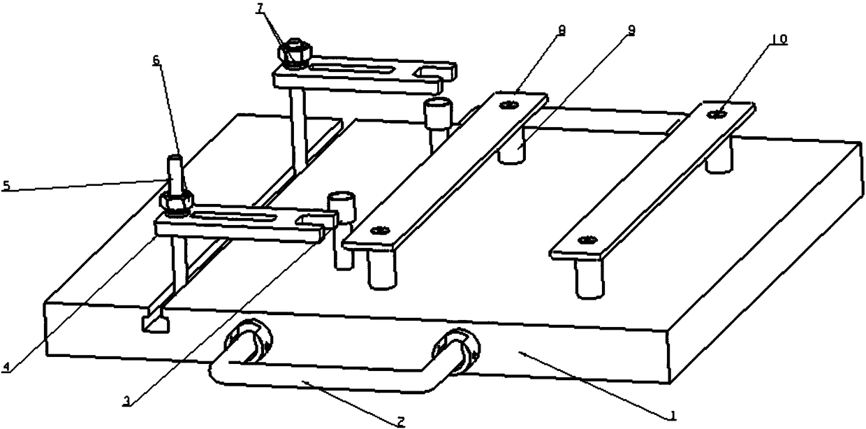
[0031] Such as figure 2 As shown, the quick release screw lock riveting tooling of this embodiment includes a base 1, a handle 2, a spacer 3, a pressure plate 4, a screw 5, a nut 6, a nut spring washer 7, a backing plate 8, a pillar 9, and a screw 10.

[0032] Among them, an inverted T-shaped groove is opened on the base 1, and the bottom of the screw rod 5 is an inverted T-shaped block. The shape and size of the inverted T-shaped block match the shape and size of the inverted T-shaped groove respectively. In the T-shaped slot and can move freely along the inverted T-shaped slot; one end of the pressure plate 4 has a threaded hole, the pressure plate 4 is screwed on the screw 5 through the threaded hole, and the nut 6...


PUM


Abstract

The invention discloses a quick-release spiral lock catch riveting tooling. The quick-release spiral lock catch riveting tooling comprises a supporting part and a riveting tool, wherein the supporting part comprises a base, and height-adjustable base plates are arranged on the base and used for supporting box boards; movable screws are also arranged on the base, and height-adjustable press plates are mounted on the screws; a height-adjustable cushion block is further arranged between each screw and the corresponding base plate, a groove with an inverted U-shaped cross section is formed in the top of the cushion block, and the size of the cushion block is matched with that of a lock nut of a quick-release spiral lock catch; an U-shaped opening is formed in one end, close to the corresponding cushion block, of each press plate; the riveting tool comprises a lengthening bar and riveting punches detachably connected with the lengthening bar, inner grooves are formed in tops of the riveting punches, outer edges are chamfered, lock pins are sleeved with the inner grooves in the tops, and flanging operation of riveting is realized under the chamfering action by the aid of external force. The quick-release spiral lock catch riveting tooling is firm in compression joint and high in practicability; if manual pressing is replaced with tooling pressing, manpower and working hours can be saved, and meanwhile, the qualification rate of riveting is increased.

Description

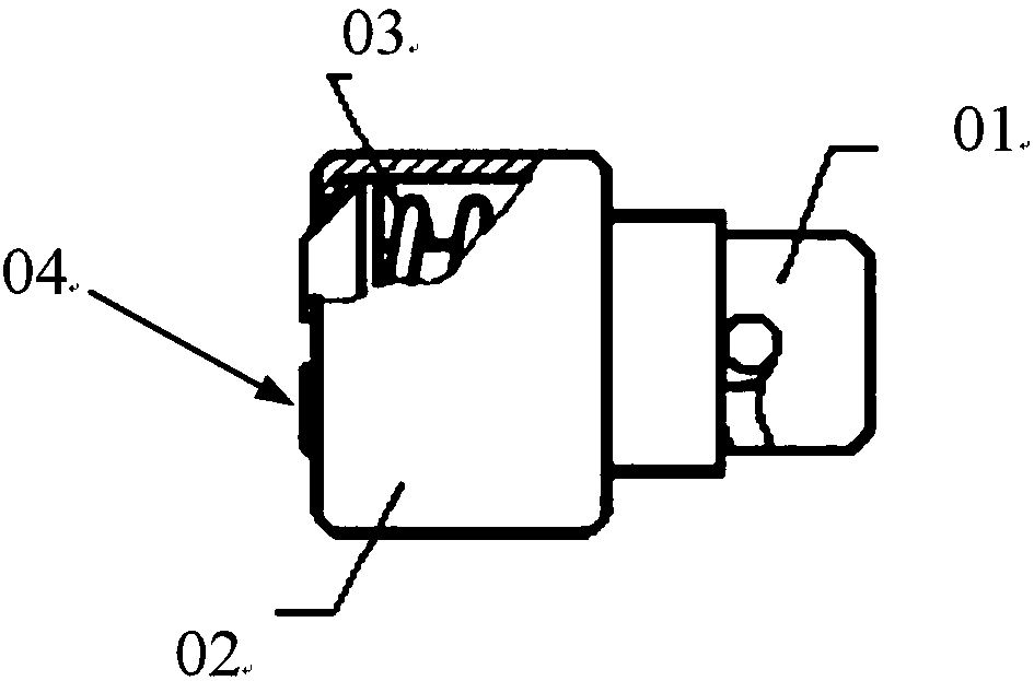
technical field [0001] The invention belongs to the technical field of tooling for equipment products in the engine room, and relates to a quick-release screw lock riveting tool for realizing high-quality riveting of quick-release screw locks on thin plates and chassis. Background technique [0002] The unloading screw lock is often used for the installation and fastening of equipment products in the engine room on the equipment bracket. The product can be turned over and riveted on the panel, which is not easy to fall off and lose. Quick release screw lock structure such as figure 1 as shown, figure 1 01 is the locking nail, 02 is the outer casing, 03 is the spring, and 04 is the lock cap. When riveting the lock buckle, it is necessary to press the nut first, compact the spring, and then turn over the side of the outer casing. The turning angle is based on the design requirements, usually 100°. [0003] At least two people are required to complete the riveting of the lo...

Claims


Application Information

Patent Timeline
Patent Type & Authority Patents(China)
IPC IPC(8): B23P19/02
CPCB23P19/02
Inventor 赵天一曹建会王双桥王怀志
Owner TIANJIN JINHANG COMP TECH RES INST
Why Eureka
Eureka Blog
Learn More