
Balancing and stabilizing mechanism on head of robot

A robot and head technology, applied in the field of robot head balance and stability mechanism, can solve the problems that the rotation balance in the vertical direction cannot be effectively guaranteed, and achieve the effects of light weight, less material, and extended service life

Inactive Publication Date: 2017-01-04
浙江梧斯源通信科技股份有限公司
View PDF7 Cites 3 Cited by
  • Summary
  • Abstract
  • Description
  • Claims
  • Application Information

AI Technical Summary

Problems solved by technology

This technical solution also has a certain effect on the balance of the robot's horizontal rotation (head-turning or head-shaking state), but it cannot effectively guarantee the balance of the vertical rotation (that is, the head-up or nodding state)

Method used


Image

  • Balancing and stabilizing mechanism on head of robot

Examples


Embodiment 1

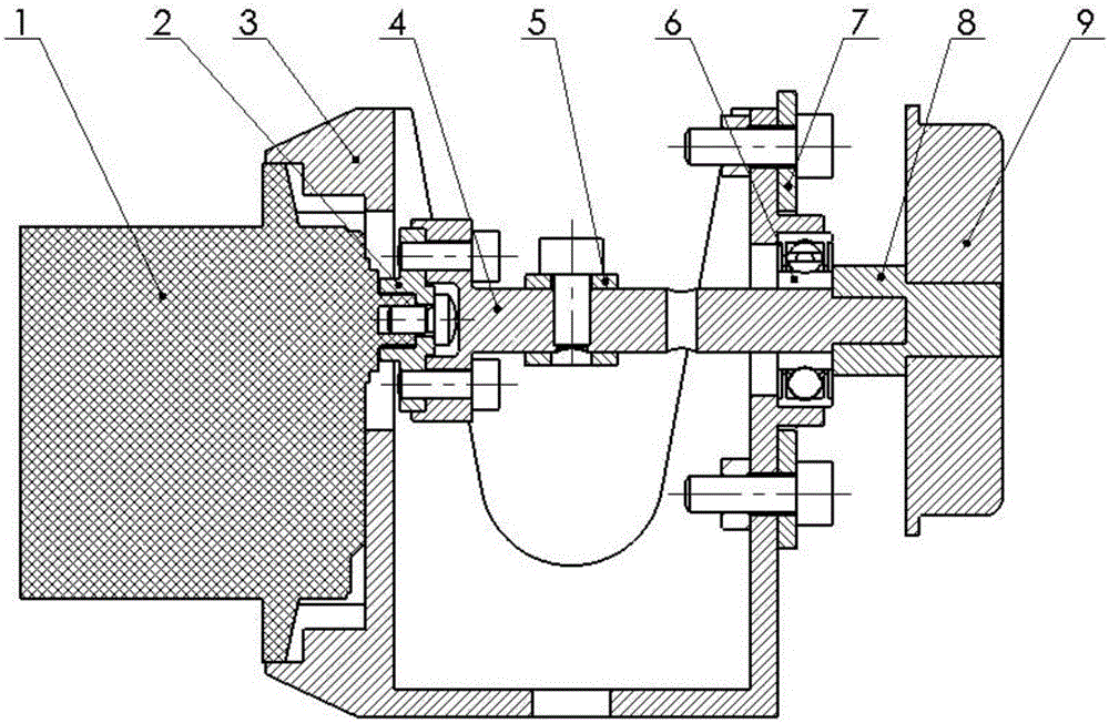
[0018] Such as figure 1 The robot head balance stabilization mechanism shown includes a frame 3, a steering gear 1 is fixed on one side of the frame 3, and a damper 9 is fixed on the other side of the frame 3. The steering gear 1 is connected to one end of the rotating shaft 4 through the steering gear adapter plate 2 , and the other end of the rotating shaft 4 is connected to the damper 9 through the damping adapter shaft 8 . The middle part of rotating shaft 4 is connected with robot head rotating rod 5. The rotating shaft 4 between the robot head rotating rod 5 and the damping adapter shaft 8 is also provided with a bearing 6 , and the bearing 6 is arranged on the frame 3 .

[0019] The steering gear 1 is used as a driving device to drive the rotating shaft 4 to rotate, and the rotating shaft 4 drives the connecting rod 5 of the robot head to rotate, thereby driving the robot head to rotate. The damper 9 increases the rotational resistance of the head as a braking device,...


PUM


Abstract

The invention relates to a balancing and stabilizing mechanism on the head of a robot, comprising a rack and a robot head connecting rod. The balancing and stabilizing mechanism is characterized by further comprising a rotating shaft connected with the robot head connecting rod. One end of the rotating shaft is connected with a steering engine through a steering engine coupling disc, and the other end is connected with a damper through a damping coupling shaft. A bearing is further arranged at the rotating shaft between the robot head connecting rod and a damping connecting shaft, and the steering engine, the bearing and the damper are arranged on the rack. The balancing and stabilizing mechanism can realize rotation of the robot head through a driving device, effectively prevent shaking during the rotation of the robot head due to eccentricity and improve the balance stability of the robot head during rotation.

Description

technical field [0001] The invention relates to the technical field of robot manufacturing, in particular to a robot head balance stabilization mechanism. Background technique [0002] The head of an intelligent robot needs to realize various actions and accurately locate various angles, such as the specific position of nodding and raising the head. Existing intelligent robots are mainly provided with a driving device, the output shaft of the driving device is directly connected with the head, and the head is driven to rotate by the driving device. The camera is located at the eyes of the robot's head, and it is required that the robot's head cannot shake during walking. However, the head mechanism is generally difficult to ensure that the center of gravity is located on the absolute rotation axis of the head, which often causes eccentricity, thereby affecting the stability of the head. Many existing solutions are often too cumbersome, or changing the drive, such as using ...

Claims


Application Information

Patent Timeline
IPC IPC(8): B25J19/00B25J9/00
CPCB25J19/0008B25J9/0009
Inventor 张加俊爨凯敏吴先鹏
Owner 浙江梧斯源通信科技股份有限公司
Learn More