Spring piece and mesh loading process equipment

A shrapnel and material feeding technology, applied in the direction of coating, etc., can solve the problems of low production stability, difficult disassembly and assembly, easy damage of shrapnel, etc., and achieve the effect of simple tooling structure, high production stability, and precise positioning

Active Publication Date: 2017-01-04
GOERTEK INC
View PDF6 Cites 4 Cited by
  • Summary
  • Abstract
  • Description
  • Claims
  • Application Information

AI Technical Summary

Problems solved by technology

[0003] At present, in the production process of some injection molding products with both shrapnel and mesh inserts, the shrapnel is usually fed by thimble ejection, and the mesh is usually fed by split suction heads. The two inserts require two different The feeding equipment increases the complexity of the equipment and the feeding process, and also has the following defects:
[0004] 1. Due to the complex structure of the shrapnel injection molded on the product or the large number of shrapnel, there are many types and quantities of thimbles, which correspondingly result in high processing costs for the feeding equipment and difficult disassembly and assembly. At the same time, the feeding accuracy of the shrapnel Low, easy to damage shrapnel
[0005] 2. Due to the fact that the mesh cloth is fed with a split suction head, the feeding accuracy of the mesh cloth is not enough, and the bad phenomena of mesh deviation and mesh leakage are serious, and it is difficult to debug the feeding equipment and the production stability is low.

Method used


Image

  • Spring piece and mesh loading process equipment
  • Spring piece and mesh loading process equipment
  • Spring piece and mesh loading process equipment

Examples


Embodiment Construction

[0031] Below in conjunction with accompanying drawing and embodiment, further elaborate the present invention.

[0032] The orientations involved in this manual are all based on the orientations of the shrapnel and mesh feeding tooling of the present invention when they are in normal operation, and do not limit their orientations during storage and transportation. They only represent relative positional relationships, not absolute positional relationships.

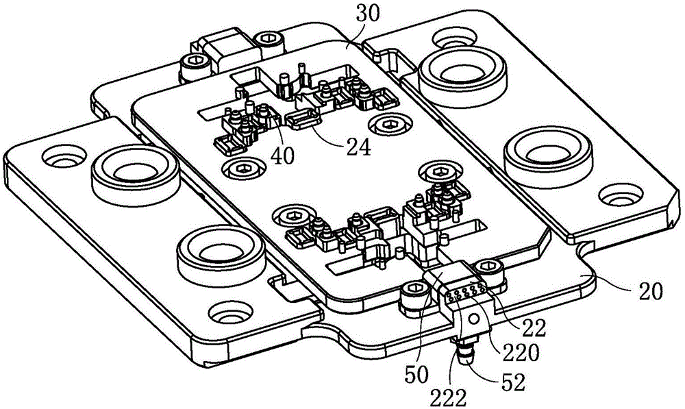
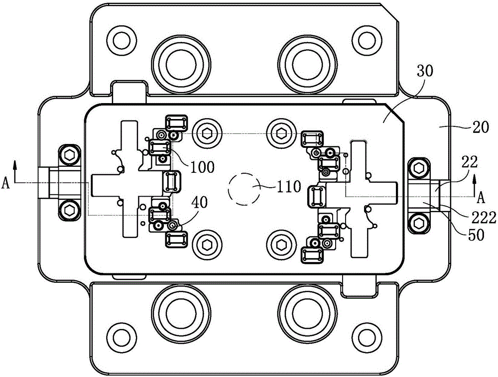
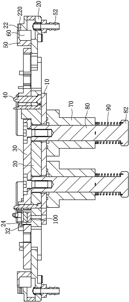
[0033] Such as figure 1 , figure 2 and image 3 As shown together, a spring and mesh feeding tooling includes a base plate 20, a plurality of spring positioning pins 40 are vertically fixed on the base plate 20, and a large hole is provided on the base plate 20 corresponding to each spring positioning pin 40. Countersunk hole, the lower end of the shrapnel positioning pin 40 is provided with a convex cap, the convex cap is located in the large hole of the countersink hole, and the lower end surface of the shrapnel posit...


PUM


Abstract

The invention discloses spring piece and mesh loading process equipment, relating to the technical field of injection molding process equipment. The process equipment comprises a bottom plate and a push plate, which are superposed together, wherein a plurality of spring piece locating pins are vertically installed on the bottom plate; the end of each spring piece locating pin passes through the push plate and protrudes out of the push plate; mesh suckers are also arranged on the bottom plate; mesh joint surfaces are arranged on the mesh suckers; a plurality of air holes are formed in the mesh suckers; one end of each air hole is arranged on the mesh joint surfaces and the other end is communicated with an air source; a bottom plate through hole is formed in the bottom plate and is used for driving a driving mechanism, moving in the vertical direction, of the push plate to pass through the bottom plate through hole. The spring piece and mesh loading process equipment has the effect of solving the technical problems of poor injection molding spring piece and mesh loading precision and low stability in the prior art, has high loading precision, high production stability and a simple structure and is low in production cost.

Description

technical field [0001] The invention relates to the technical field of injection molding tooling, in particular to a loading tooling for shrapnel and mesh cloth for injection molding. Background technique [0002] Injection molding process refers to the process of making molten raw materials into products of a certain shape through operations such as pressurization, injection, cooling, and detachment. There are many types of injection molding products, and there are pure plastic products with a slightly simpler process and mold structure. , there are also products with inserts with complex process and mold structure. The inserts include steel sheets, shrapnel and mesh cloth. When injection molding, various inserts need corresponding feeding equipment to feed them into the injection mold. middle. [0003] At present, in the production process of some injection molding products with both shrapnel and mesh inserts, the shrapnel is usually fed by thimble ejection, and the mesh ...

Claims


Application Information

Patent Timeline
Patent Type & Authority Applications(China)
IPC IPC(8): B29C45/14
CPCB29C45/14008
Inventor 李德运张烨刘佳张华贞赵永梅冯公杰孙伟洋邱远灏
Owner GOERTEK INC
Why Eureka
Try Eureka