Supply device and air blowing feeding equipment
A feeding device and feeding technology, applied in conveyors, transportation and packaging, conveying bulk materials, etc., can solve problems such as troublesome operation and increased production costs
- Summary
- Abstract
- Description
- Claims
- Application Information
AI Technical Summary
Problems solved by technology
Method used
Image
Examples
Embodiment 1
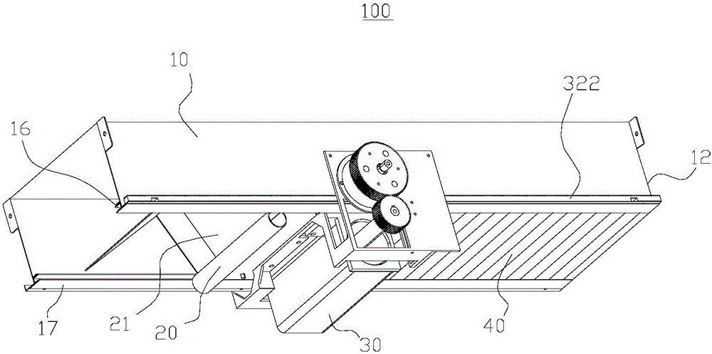
[0040] Such as figure 1 As shown, this embodiment provides a feeding device 100 , including a feeding tube 10 , a sliding body 20 , a first driving device 30 and a shielding software 40 .
[0041] Among them, such as figure 2 As shown, the feeding pipe 10 is a square pipe, which includes a first side wall 101, a top wall 102 and a second side wall 103, and the first side wall 101, the top wall 102 and the second side wall 103 are sequentially connected to form a U-shaped structure. The inside of the feeding pipe 10 enclosed by the first side wall 101, the top wall 102 and the second side wall 103 forms a feeding channel 11, and one end of the feeding tube 10 is a feeding port 12, and the feeding port 12 and the feeding channel 11 connected. An opening 15 is formed at the bottom of the feeding pipe 10 surrounded by the first side wall 101 , the top wall 102 and the second side wall 103 , and the opening 15 communicates with the feeding channel 11 .
[0042]The first guide r...
Embodiment 2
[0055] The material supply device 100 provided by the embodiment of the present invention has the same realization principle and technical effect as the foregoing method embodiment. For brief description, for the parts not mentioned in the device embodiment part, reference may be made to the foregoing method embodiment Corresponding content.
[0056] Such as Figure 8 As shown, the difference between the feeding device 100 provided in this embodiment and the above embodiments is that it also includes a roller blind device 50 .
[0057] Such as Figure 9 As shown, the roller blind device 50 includes a roller 51 and a second driving device 52, the second driving device 52 is a motor, the roller 51 is connected to the feeding pipe 10 in rotation, the motor is fixedly connected to the feeding pipe 10, and the motor is used to drive the roller 51 to feed material Pipe 10 rotates, and the transmission mode between motor and cylinder 51 is belt transmission.
[0058] In this embod...
Embodiment 3
[0063] Such as Figure 10 As shown, this embodiment provides a blowing and feeding device 200, including a frame 201, a blowing device 202 and the feeding device 100 in the above-mentioned embodiments.
[0064] Wherein, the frame 201 mainly plays a supporting role, and its structure is not limited. In this embodiment, the frame 201 is a frame structure, and rollers are provided at the bottom thereof.
[0065] The blowing device 202 has a blowing port 2021, and the blowing device 202 is used to supply materials, and the materials will be ejected from the blowing port 2021 when the blowing device is working.
[0066] Blowing device 202 is fixed on the frame 201, and the blowing outlet 2021 of blowing device 202 is arranged upwards, and blowing device 202 is connected with feeding device 100 by right-angle elbow 203, and right-angle elbow 203 is with the blowing outlet 2021 of blowing device 202 and the supplying device. The feeding port 12 of the feeding pipe 10 in the feeding ...
PUM
 Abstract
Description
Claims
Application Information
 - R&D
- Intellectual Property
- Life Sciences
- Materials
- Tech Scout
- Unparalleled Data Quality
- Higher Quality Content
- 60% Fewer Hallucinations
Browse by: Latest US Patents, China's latest patents, Technical Efficacy Thesaurus, Application Domain, Technology Topic, Popular Technical Reports.
© 2025 PatSnap. All rights reserved.Legal|Privacy policy|Modern Slavery Act Transparency Statement|Sitemap|About US| Contact US: help@patsnap.com


