Eureka AIR delivers breakthrough ideas for toughest innovation challenges, trusted by R&D personnel around the world.

Stranding cage type spiral conveyor

A screw conveyor and twisted cage technology, which is applied in the field of powder conveying system in thermal power plants, can solve the problems of unsuitable for super long-distance conveying materials, poor neutrality, poor energy saving and environmental protection effects, etc.

Inactive Publication Date: 2018-04-17
GUANGZHOU KAILILAI ELECTRICAL MACHINERY CO LTD
View PDF0 Cites 0 Cited by
  • Summary
  • Abstract
  • Description
  • Claims
  • Application Information

AI Technical Summary

Problems solved by technology

Among them, for the U-shaped screw conveyor, the barrel body is "U"-shaped, and the bearing seat is suspended and fixed on both sides of the barrel body. The neutrality is poor, and it is easy to cause the shaft to be stuck, the bearing seal is not tight, and the noise is large. and other defects, and it is not suitable to transport materials over a long distance; 2. The scraper type conveyor scrapes the slag at the bottom of the barrel to the discharge port through a cast chain and a scraper, and the upper part of the barrel is equipped with a return track
The scraper chain of this equipment is not only in frictional contact with the bottom track of the barrel, but also in frictional contact with the slag, so the scraper chain and the sprocket wear block generate quite a lot of noise, and at the same time require a large electrical load, and it is not suitable for super long distance conveying materials
[0003] For the above two conveyors, in the actual use process, they have the following defects, specifically: high equipment failure rate, high frequency of wear parts replacement, large amount of equipment maintenance, short service life of equipment, low energy saving and environmental protection effect Difference

Method used


Image

  • Stranding cage type spiral conveyor
  • Stranding cage type spiral conveyor

Examples


Embodiment Construction

[0029] The present invention will be described below in conjunction with specific embodiments.

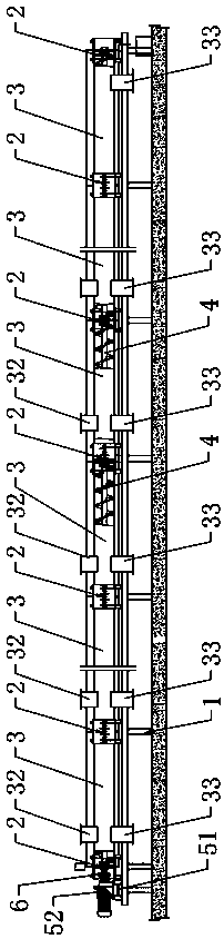
[0030] Such as figure 1 and figure 2 As shown, a twisted cage screw conveyor includes a frame 1, the upper end of the frame 1 is equipped with at least three embedded bearing seats 2 arranged at intervals from front to back, and two adjacent embedded Between the bearing housings 2, there is an intermediate box 3 arranged horizontally along the front-to-back direction and having an "O" shape in the vertical section. Each intermediate box 3 is provided with an intermediate conveying cavity that completely penetrates along the front-to-back direction. Room 31.

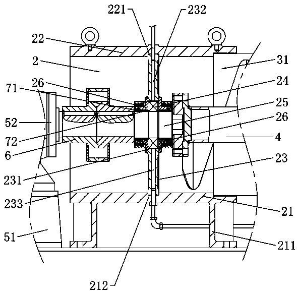
[0031] Further, the embedded bearing housing 2 includes a lower bearing housing body 21 in the shape of a semi-circular arc, an upper bearing housing body 22 located directly above the lower housing body 21, the upper end edge of the lower bearing housing body 21 and the upper bearing housing body 22 The lower edge of the ...


PUM


Abstract

The invention discloses a twisted cage type screw conveyor, the frame of which is equipped with at least three embedded bearing seats spaced sequentially from front to back, and intermediate boxes are installed between adjacent two embedded bearing seats, and each intermediate Screw shafts are respectively embedded in the middle conveying chamber inside the box; the embedded bearing seat includes the lower body of the bearing seat and the upper body of the bearing seat which are screwed to each other. A bearing support plate is provided, and the edge of the bearing support plate is respectively embedded in the upper arc-shaped groove of the upper body of the bearing seat and the lower arc-shaped groove of the lower body of the bearing seat, and a deep groove is embedded in the bearing installation through hole at the middle position of the bearing support plate. The center hole of the ball bearing and deep groove ball bearing is embedded with a movable shaft; each intermediate box is respectively equipped with a material inlet and a material outlet, and the frontmost movable shaft is driven by a deceleration drive motor. The invention has the advantages of novel design, good stability and reliability, and can realize long-distance conveying operation and multi-point feeding.

Description

technical field [0001] The invention relates to the technical field of powder delivery systems in thermal power plants, in particular to a twisted cage screw conveyor. Background technique [0002] At present, the dust removal methods commonly used at the coal drop point of the belt conveyor in thermal power plants generally adopt: 1. U-shaped screw conveyor; 2. Scraper conveyor. Among them, for the U-shaped screw conveyor, the barrel body is "U"-shaped, and the bearing seat is suspended and fixed on both sides of the barrel body. The neutrality is poor, and it is easy to cause the shaft to be stuck, the bearing seal is not tight, and the noise is large. 2. The scraper type conveyor scrapes the slag at the bottom of the barrel to the discharge port through the cast chain and scraper, and the upper part of the barrel is equipped with a return track. The scraper chain of this equipment is not only in frictional contact with the bottom track of the barrel, but also in friction...

Claims


Application Information

Patent Timeline
Patent Type & Authority Applications(China)
IPC IPC(8): B65G33/32B65G33/24B65G33/14
CPCB65G33/32B65G33/14B65G33/24
Inventor 胡庆雄
Owner GUANGZHOU KAILILAI ELECTRICAL MACHINERY CO LTD
Why Eureka
Eureka Blog
Learn More