An improved ceramic rod for the lower wheel of the yarn storage wheel, the lower wheel of the yarn storage wheel and the yarn storage wheel

A technology of ceramic rod and yarn storage wheel, applied in textile and papermaking, knitting, weft knitting and other directions, can solve the problems of fluff, easy aggregation of yarn or fluff, yarn breakage, etc., to reduce labor intensity Effect

Active Publication Date: 2019-04-23
XIAMEN LINK KUITTING MACHINE ACCESSORY
View PDF10 Cites 0 Cited by
  • Summary
  • Abstract
  • Description
  • Claims
  • Application Information

AI Technical Summary

Problems solved by technology

[0002] The yarn storage wheel is an important component of the yarn storage and feeder of the knitting machine, such as figure 1 As shown, most of the commonly used yarn storage wheels include an upper wheel 11', a lower wheel 12' and a plurality of steel columns 13', and the plurality of steel columns 13' are arranged in a cylindrical shape at intervals, and the two ends of the steel columns 13' are respectively Press into the upper rim 111' and the lower rim 121' for positioning. With the above structure, there are the following problems: 1. The yarn is wrapped around the steel column 13' of the yarn storage wheel. In long-term use, the steel column 13' and the yarn The contact surface of the thread is easy to produce fine wear marks, and these wear marks will further cause the yarn (especially chemical fiber materials, such as polyester, etc.) Yarn, or the yarn made of several strands of spun yarn, some of which are broken; the broken yarn or fluff is easy to gather at the bottom 131' of the inner concave part of the steel column 13', which needs to be done manually with the help of external tools. to clean up

Method used


Image

  • An improved ceramic rod for the lower wheel of the yarn storage wheel, the lower wheel of the yarn storage wheel and the yarn storage wheel
  • An improved ceramic rod for the lower wheel of the yarn storage wheel, the lower wheel of the yarn storage wheel and the yarn storage wheel
  • An improved ceramic rod for the lower wheel of the yarn storage wheel, the lower wheel of the yarn storage wheel and the yarn storage wheel

Examples


Embodiment Construction

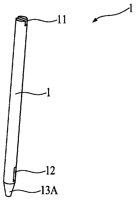
[0028] Such as figure 2 As shown, the ceramic rod of the first yarn storage wheel lower wheel of the present invention, the ceramic rod 1 is a round rod, and its top is provided with a positioning groove 11, the positioning groove is in-line or cross-shaped, and the inner part of the ceramic rod 1 At least one covering groove 12 is provided. By setting the positioning groove 11, when the ceramic rod 1 is assembled with the lower wheel of the yarn storage wheel, the covering groove is located in the arc surface of the inner groove of the lower wheel of the yarn storage wheel, so that The outer arc surface of the ceramic rod 1 can be in contact with the yarn; regarding the setting of the number of coating grooves, the present embodiment preferably has two coating grooves 12, and the two coating grooves 12 are symmetrical along the ceramic rod 1 left and right, up and down. Arranged in a staggered manner, the depth of the coating groove 12 ≤ the radius of the ceramic rod 1, sinc...


PUM


Abstract

The invention discloses a yarn storage wheel lower wheel ceramic rod. A positioning groove is formed in the top of the ceramic rod. The inner side portion of the ceramic rod is provided with at least one wrapping groove. The surface, making contact with yarn, of the ceramic rod is an arc surface. The radial size of the lower portion of the ceramic rod is gradually decreased so that a guiding face with the gradually-decreased diameter can be formed. Due to the fact that the surface, making contact with the yarn, of the ceramic rod is the arc surface, the radial size of the lower portion of the ceramic rod is gradually decreased so that the guiding face with the gradually-decreased diameter can be formed; the middle of the ceramic rod with the gradually-decreased lower radial size is still larger than the lower portion of the ceramic rod, so that broken yarn can slide down freely, the yarn is broken or generated flocks will not be gathered at the intersection between the middle yarn portion and the yarn outlet guiding portion, and the labor intensity of manual cleaning is greatly lowered.

Description

technical field [0001] The invention relates to the field of textiles, in particular to a ceramic rod for the lower wheel of the yarn storage wheel, the lower wheel of the yarn storage wheel and an improved structure of the yarn storage wheel. Background technique [0002] The yarn storage wheel is an important component of the yarn storage and feeder of the knitting machine, such as figure 1 As shown, most of the commonly used yarn storage wheels include an upper wheel 11', a lower wheel 12' and a plurality of steel columns 13', and the plurality of steel columns 13' are arranged in a cylindrical shape at intervals, and the two ends of the steel columns 13' are respectively Press into the upper rim 111' and the lower rim 121' for positioning. With the above structure, there are the following problems: 1. The yarn is wrapped around the steel column 13' of the yarn storage wheel. In long-term use, the steel column 13' and the yarn The contact surface of the thread is easy to...

Claims


Application Information

Patent Timeline
Patent Type & Authority Patents(China)
IPC IPC(8): D04B15/38
CPCD04B15/38
Inventor 李俊贤
Owner XIAMEN LINK KUITTING MACHINE ACCESSORY
Why Eureka
Try Eureka