engine intake manifold

An intake manifold and engine technology, applied to combustion engines, engine components, machines/engines, etc., can solve problems such as uneven air intake in intake branch pipes, increased engine vibration and noise, increased fuel consumption and emissions, etc., to achieve a solution The effect of uneven air intake, reduced fuel consumption, and reduced exhaust emissions

Active Publication Date: 2019-03-26
ANHUI JIANGHUAI AUTOMOBILE GRP CORP LTD
View PDF5 Cites 0 Cited by
  • Summary
  • Abstract
  • Description
  • Claims
  • Application Information

AI Technical Summary

Problems solved by technology

This structure easily leads to uneven air intake of each intake branch pipe, resulting in poor combustion, increased engine vibration and noise, and increased fuel consumption and emissions

Method used


Image

  • engine intake manifold
  • engine intake manifold
  • engine intake manifold

Examples


Embodiment Construction

[0027] Embodiments of the present invention are described in detail below, examples of which are shown in the drawings, wherein the same or similar reference numerals designate the same or similar elements or elements having the same or similar functions throughout. The embodiments described below by referring to the figures are exemplary only for explaining the present invention and should not be construed as limiting the present invention.

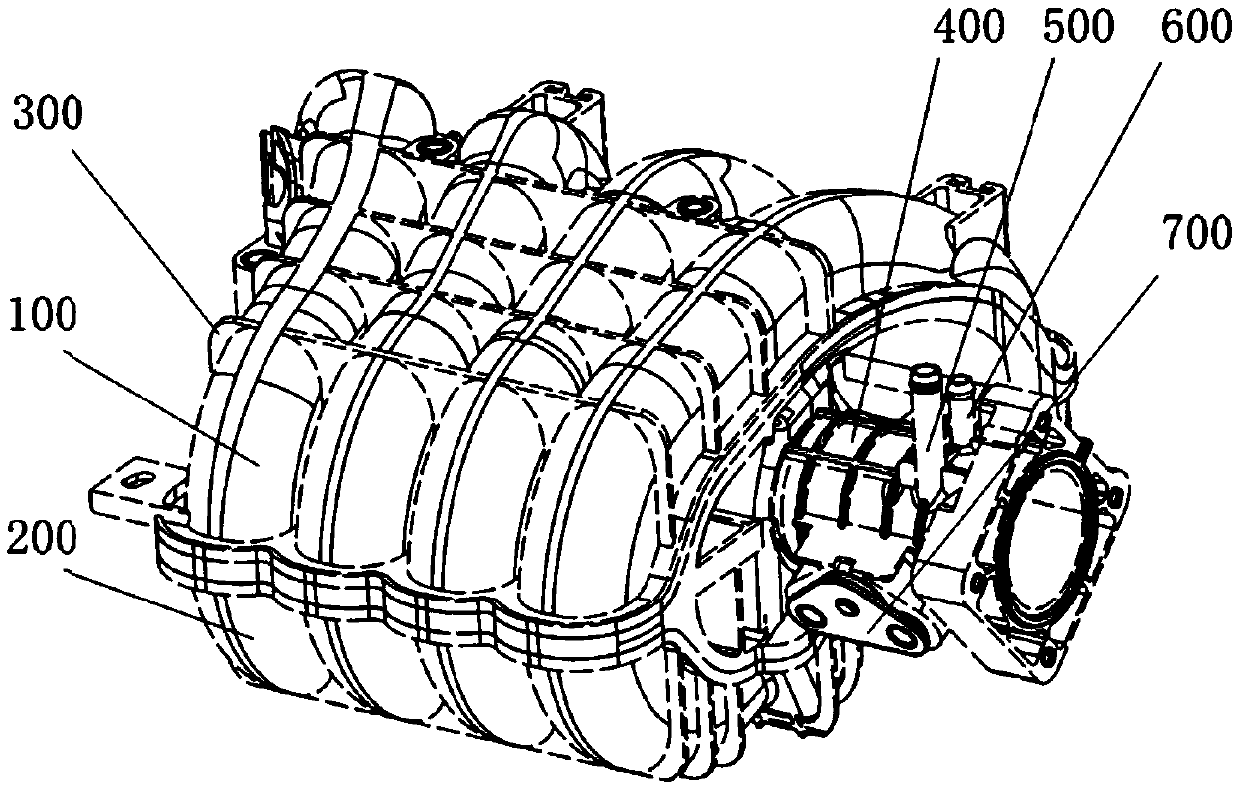
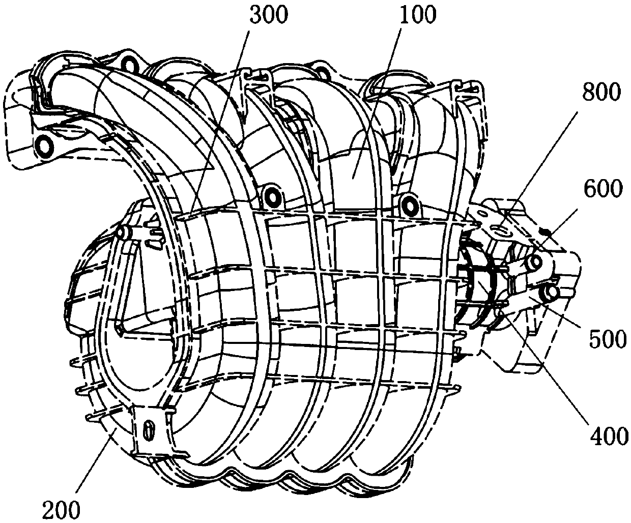
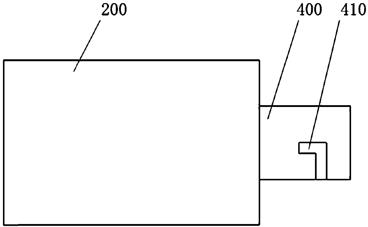
[0028] figure 1 An axonometric view of an engine intake manifold provided by an embodiment of the present invention at a first angle, and Fig. 2 is an axonometric view of an engine intake manifold provided by an embodiment of the present invention at a second angle, image 3 It is a schematic diagram of the structure of the exhaust pipe installed in the intake manifold, Figure 4 It is a schematic diagram of the structure of the deflector arranged in the plenum.

[0029] Please also refer to figure 1 and Figure 4 , the embodiment of...


PUM


Abstract

The invention discloses an engine intake manifold. The engine intake manifold comprises an intake main pipe, an intake branch pipe and a pressure stabilizing cavity; the intake main pipe is communicated with the pressure stabilizing cavity; and an intake port of the intake branch pipe is communicated with the pressure stabilizing cavity. The engine intake manifold further comprises a waste gas recirculating system and a guide plate, wherein the waste gas recirculating system includes a waste gas pipe; the waste gas pipe is fixed on the intake main pipe, and is communicated with the intake main pipe; the guide plate is perpendicular to the axis direction of the pressure stabilizing cavity; and one end of the guide plate is fixed on the inner wall of the pressure stabilizing cavity near the intake main pipe, and the other end of the guide plate keeps a set distance from the inner wall of the pressure stabilizing cavity. The engine intake manifold realizes the purposes of reduction of oil consumption and waste gas discharge through setting of the waste gas pipe and the guide plate, solves the problem of nonuniform intake quantity of each intake branch pipe, and guarantees the combustion quality in a cylinder.

Description

technical field [0001] The invention relates to the technical field of engines, in particular to an engine intake manifold. Background technique [0002] At present, exhaust gas recirculation technology is mainly used in some diesel engine intake systems, but less in gasoline engine intake systems. The main purpose of applying exhaust gas recirculation technology in the diesel engine intake system is to reduce the combustion temperature in the cylinder, thereby reducing the emission of nitrogen oxides. Since the exhaust gas recirculation technology is rarely used in the intake manifold of the existing gasoline engine, it cannot control the emission of nitrogen oxides; in addition, no fuel-saving measures are applied, so it cannot provide support for reducing the fuel consumption of the engine or the whole vehicle. [0003] In addition, in the intake manifold with exhaust gas recirculation, the exhaust gas is introduced from the intake manifold, and then enters the plenum, a...

Claims


Application Information

Patent Timeline
Patent Type & Authority Patents(China)
IPC IPC(8): F02M35/104F02B37/02
CPCF02B37/02F02M35/104Y02T10/12
Inventor 张超杨林强常耀红王军穆立侠叶志伟王次安王强姚炜雷蕾谈健
Owner ANHUI JIANGHUAI AUTOMOBILE GRP CORP LTD
Why Eureka
Try Eureka