Intelligent faucet

A faucet and intelligent technology, applied in the direction of valve details, engine components, valve operation/release devices, etc., can solve problems such as the impact of product aesthetics, and achieve the effects of improving labor production efficiency, convenient product maintenance, and strong practicability

Inactive Publication Date: 2017-01-04
温州得享家居科技有限公司
View PDF4 Cites 0 Cited by
  • Summary
  • Abstract
  • Description
  • Claims
  • Application Information

AI Technical Summary

Problems solved by technology

Although this method solves the problem of reducing the internal space requirements of the faucet and facilitates after-sales maintenance, the aesthetics of the product is greatly affected.

Method used


Image

  • Intelligent faucet

Examples


Embodiment Construction

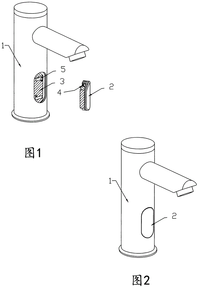
[0011] Referring to the accompanying drawings, the faucet has a body (1), a sensor (2), and a supporting surface (3) is provided in the body (1), and it is characterized in that a magnet (4) is arranged on the sensor (2), and the magnet (4 ) is located on the back of the sensor (2), and an iron sheet (5) is arranged on the support surface (3), and the iron sheet (5) is located at a position close to the magnet (4) and the support surface (3). The iron sheet (5) can be a magnet or other metals that can be magnetized. Said magnet (4) can be a kind of other metal which can be magnetized.

[0012] When the present invention is applied, taking the assembly of the smart faucet as an example, first install the inner support surface (3) of the faucet in place, then fix the iron sheet (5) to the support surface (3) and place the magnet (4) on the sensor (2). ) corresponding position, and then the magnet (4) is installed in the specified slot on the back of the sensor (2), because the ...


PUM


Abstract

The invention discloses an intelligent faucet. The intelligent faucet is provided with a body (1) and a sensor (2). A support face (3) is arranged in the body (1). The intelligent faucet is characterized in that the sensor (2) is provided with a magnet (4) located on the back face of the sensor (2); and the support face (3) is provided with an iron piece (5) located in the position, close to the support face (3), of the magnet (4). The intelligent faucet is high in practicability and significant in technological innovation and provides great effects for improving labor production efficiency and facilitating product maintenance.

Description

technical field [0001] The invention relates to an improved invention of a water supply valve device, in particular to an intelligent faucet. Background technique [0002] Currently produced smart faucets, especially smart faucets with sensors installed directly in the main body of the faucet, there are two ways to install the sensor to the main body of the faucet according to the prior art. One is to install the sensor from the inside to the outside. The disadvantage of this installation method is that there is a greater requirement for the internal space of the faucet, and when the sensor is repaired and replaced, the faucet needs to be removed as a whole, which increases the difficulty of after-sales maintenance. Another way to install the sensor is to install from the outside to the inside, and this installation method is to use the screw mounting hole on the front of the sensor, fix it with screws, and then cover the mounting hole with a decorative cap. Although this m...

Claims


Application Information

Patent Timeline
Patent Type & Authority Applications(China)
IPC IPC(8): F16K31/02F16K51/00
CPCF16K31/02F16K51/00
Inventor 陈震宇
Owner 温州得享家居科技有限公司
Why Eureka
Try Eureka