LED light guide lens

A lens and strip technology, applied in the field of LED lighting, can solve the problems of blood-like clutter, reduce the light mixing efficiency of the light guide lens, etc., and achieve the effect of good light mixing and elimination of blood-like clutter.

Inactive Publication Date: 2017-01-04
GUANGZHOU YIXIN ENERGY SAVING SERVICE
View PDF4 Cites 5 Cited by
  • Summary
  • Abstract
  • Description
  • Claims
  • Application Information

AI Technical Summary

Problems solved by technology

[0003] Most of the existing light guide lenses are long strips. However, when the light is mixed with the long light guide lens, various blood-like spots will appear. At present, in order to solve the problem that the long light guide lens For the problem of blood-streaked spots, in the prior art, the light-mixing frosted structure is often set at the light-emitting position of the elongated light guide lens to solve the problem of blood-streaked spots, but it reduces the The light mixing efficiency is counterproductive

Method used


Image

  • LED light guide lens
  • LED light guide lens
  • LED light guide lens

Examples


Embodiment 1

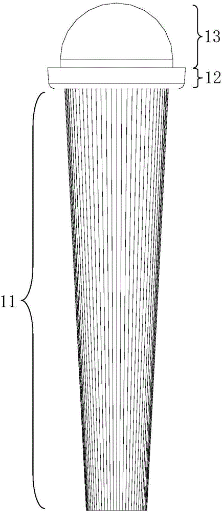
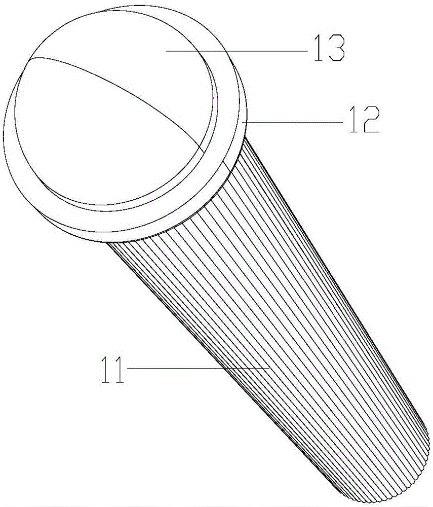
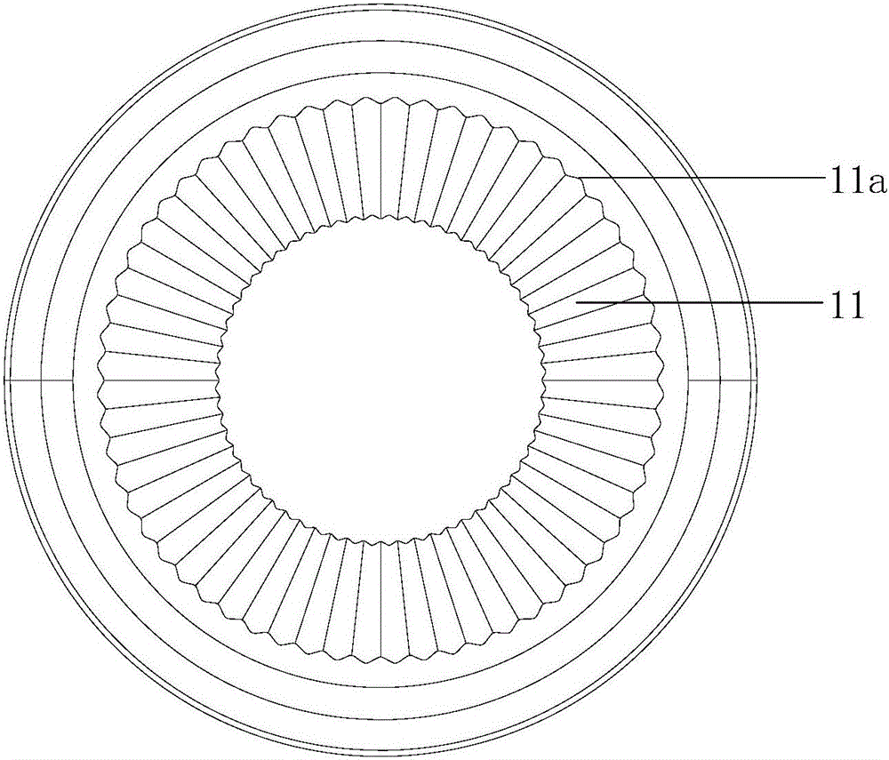
[0034] see figure 1 , figure 2 and image 3 , an LED light guide lens of the present invention, the LED light guide lens is rotationally symmetrical, and includes a long columnar body 11, a flat cylinder 12 and a hemisphere 13 connected in sequence; the long columnar body 11 moves from one end to the other One end gradually becomes larger, and the side of the elongated columnar body 11 is provided with annular wavy fine lines 11a, and the annular wavy fine lines 11a are opposite to the elongated columnar body from the relatively small end of the elongated columnar body The large end extends, and the ring-shaped wavy fine lines 11a are rotationally symmetrical;

[0035] The relatively large end of the elongated columnar body 11 is connected to a flat cylinder 12, and the other end of the flat cylinder 12 is connected to a hemisphere 13. The spherical surface or smooth curved surface of the hemisphere 13 is the light-emitting surface of the LED light guide lens of the present...

Embodiment 2

[0042] see Figure 4 , Figure 5 , Figure 8 and Figure 9 The difference between this embodiment and Embodiment 1 is that the elongated columnar body 11 is polished at the part close to the flat cylinder 12 to have a smooth surface, and the length of the polished portion of the elongated columnar body 11 is elongated 1 / 4 to 1 / 3 of the length of the cylindrical body 11 of shape.

[0043] The elongated columnar body 11 of the LED light guide lens is polished near the flat cylinder 12 because the radial structure will be deformed during processing, and the zoom stroke of the LED light guide lens is limited when the LED light guide lens is used with the zoom lens. The process is equivalent to the zoom lens imaging at different heights of the LED light guide lens, which will image the deformation of the light caused by this processing defect, and the elongated columnar body 11 is polished on the part close to the flat cylinder 12 The method can change the imaging area into a s...


PUM


Abstract

The invention discloses an LED light guide lens. The LED light guide lens comprises a long-strip-shaped cylindrical body, a flat cylinder and a hemispheroid which are sequentially connected; the long-strip-shaped cylindrical body is gradually increased from one end to the other end; the relatively large end of the long-strip-shaped cylindrical body is connected with the flat cylinder; the other end of the flat cylinder is connected with the hemispheroid; the spherical surface or the smooth curved surface of the hemispheroid is a light outlet surface of the LED light guide lens; the long-strip-shaped cylindrical body, the flat cylinder and the hemispheroid are coaxially; annular wave shaped fine grains are arranged on the side surface of the long-strip-shaped cylindrical body and the annular wave shaped fine grains extend from the relatively small end of the long-strip-shaped cylindrical body to the relatively large end of the long-strip-shaped cylindrical body, and the annular wave shaped fine grains are rotatably symmetrical; and the LED light guide lens is rotatably symmetrical. According to the LED light guide lens disclosed by the invention, light is mixed by the annular wave shaped fine grains, so that good light mixing is realized; and the problem that the original light guide lens has hybrid blood streak shaped varied spots during light mixing can be eliminated.

Description

technical field [0001] The invention relates to the technical field of LED lighting fixtures, in particular to an LED light guide lens. Background technique [0002] The lens is made according to the law of refraction and reflection of light, and is used to achieve the purpose of changing the light field distribution according to the will. Lenses are classified according to the effect of changing the light field, and can usually be divided into three categories: converging lenses (such as convex lenses, etc.), diverging lenses (such as concave lenses, etc.), and free-form lenses (such as asymmetric light distribution lenses, street lamp lenses, etc. ). [0003] Most of the existing light guide lenses are long strips. However, when the light is mixed with the long light guide lens, various blood-like spots will appear. At present, in order to solve the problem that the long light guide lens For the problem of blood-streaked spots, in the prior art, the light-mixing frosted ...

Claims


Application Information

Patent Timeline
Patent Type & Authority Applications(China)
IPC IPC(8): F21K9/69F21V5/04F21Y115/10
CPCF21V5/04
Inventor 朱道勇罗滔凌敏捷周烨
Owner GUANGZHOU YIXIN ENERGY SAVING SERVICE
Why Eureka
Try Eureka