Eureka AIR delivers breakthrough ideas for toughest innovation challenges, trusted by R&D personnel around the world.

A kind of backlight module and liquid crystal display

A liquid crystal display and backlight module technology, which is applied in the fields of instruments, optics, nonlinear optics, etc., can solve the problems of unsatisfactory local light control effect, affecting the quality of display products, uneven brightness and darkness of diffuser plates, etc., to improve display quality. , to achieve thin design, improve the effect of brightness

Active Publication Date: 2020-05-19
TCL CHINA STAR OPTOELECTRONICS TECH CO LTD
View PDF4 Cites 0 Cited by
  • Summary
  • Abstract
  • Description
  • Claims
  • Application Information

AI Technical Summary

Problems solved by technology

Ordinary direct-lit backlight modules mostly use closely arranged multiple LEDs or LEDs with lenses as light sources. The light from these two light sources is not restricted in the light mixing cavity of the backlight module, and often some of the light is directly or It spreads to other areas through reflection, affecting the luminous effect; at the same time, whether it is a multi-LED arrangement scheme or a secondary lens scheme, the light projection is circular, and the projections of adjacent LEDs on the diffusion plate cannot be merged, and the diffusion plate The phenomenon of uneven brightness and darkness often occurs. At the same time, although the existing direct-lit backlight module can realize local light control, the local light control effect is not ideal, which greatly affects the product quality of the display.

Method used


Image

  • A kind of backlight module and liquid crystal display
  • A kind of backlight module and liquid crystal display
  • A kind of backlight module and liquid crystal display

Examples


Embodiment Construction

[0026] The content of the present invention will be described in detail below in conjunction with the accompanying drawings. The words "up", "down", "left" and "right" are all relative to the directions shown in the drawings and should not be construed as limiting the present invention.

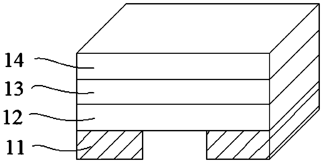
[0027] figure 1 It is a structural schematic diagram of a four-sided light-emitting LED in the prior art. Usually, a four-sided light-emitting LED is connected to a printed circuit board through a metal electrode 11, and the working mode of the four-sided light-emitting LED is controlled through the printed circuit board.

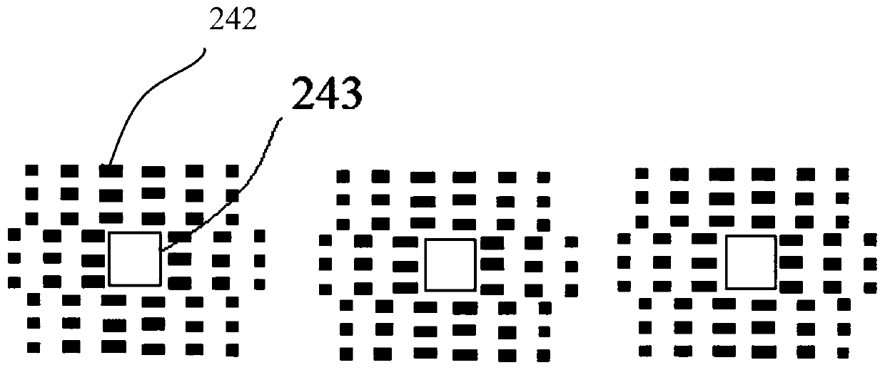
[0028] figure 2 It is a schematic structural diagram of the backlight module 20 proposed by the present invention, from figure 2It can be seen from the figure that the backlight module includes a printed circuit board 21, a reflective sheet 22, an LED light source 23, and a diffuser plate 24 from bottom to top, wherein the reflective sheet 22 is arranged on the first su...


PUM

PropertyMeasurementUnit
reflectanceaaaaaaaaaa

Abstract

The invention relates to the technical field of liquid crystal display, in particular to a backlight module and a liquid crystal displayer. The backlight module sequentially comprises a printed circuit board, a reflector plate, an LED light source and a diffusion plate from bottom to top. First protruding points are arranged on the light-in face, facing the LED light source, of the diffusion plate and around the projection, within the light-in face, of the LED light source. The first protruding points can conduct reflection diffusion on an illumination area, on the diffusion plate, of the LED light source, eliminate projection dark spaces and prevent light source gathering, so that the distribution of a light-emitting area on the diffusion plate is more uniform. Meanwhile, the LED light source can be independently controlled, local light control can be better achieved, and accordingly the display quality of a high-dynamic-comparison image is improved. The reflector plate can reflect leaking light again so that the light can irradiate the diffusion plate again, accordingly the utilization rate of the light source is increased, the light mixing distance is increased, and thinning design of the liquid crystal displayer is achieved easily.

Description

technical field [0001] The invention relates to the technical field of liquid crystal display, in particular to a backlight module and a liquid crystal display. Background technique [0002] At present, the penetration rate of LED as a backlight in the field of liquid crystal panel display has exceeded 90%. There are mainly two types of backlight module architectures: side-type and direct-type. The side-type LED backlight is to install the LED light source on the side of the light guide plate. Scattering directs the light out, the disadvantage of which is that the resulting picture contrast is relatively poor and local dimming is not possible. The direct-lit LED backlight can present images more accurately, and exhibit excellent color and light-dark contrast effects, which has gradually become the mainstream trend in the market. [0003] The direct type LED backlight module generally includes an LCD display, a diffuser plate and a PCB board. There are several packaged LED ...

Claims


Application Information

Patent Timeline
Patent Type & Authority Patents(China)
IPC IPC(8): G02F1/13357
CPCG02F1/133603G02F1/133605G02F1/133606G02F1/133607
Inventor 樊勇
Owner TCL CHINA STAR OPTOELECTRONICS TECH CO LTD
Why Eureka
Eureka Blog
Learn More