Multi-cavity LED street lamp

A LED street lamp and multi-cavity technology, applied in circuit layout, semiconductor devices of light-emitting elements, lighting and heating equipment, etc., can solve problems such as single light distribution form, low light energy utilization rate, and inability to carry out overall optical design. Achieve the effects of improving light distribution efficiency, high light energy utilization rate, and reducing labor maintenance costs

Pending Publication Date: 2017-01-04
JIANGXI GENERAL ENERGY SAVING TECH
View PDF8 Cites 0 Cited by
  • Summary
  • Abstract
  • Description
  • Claims
  • Application Information

AI Technical Summary

Problems solved by technology

[0005] What the present invention aims to solve is the technical problem of low energy utilization rate of existing LED street lighting, single light distribution form, and inability to carry out overall optical design, and provides a multi-cavity LED street lamp that is convenient for high light energy utilization rate and can be integrated optical design

Method used


Image

  • Multi-cavity LED street lamp
  • Multi-cavity LED street lamp
  • Multi-cavity LED street lamp

Examples


Embodiment 1

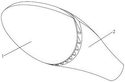
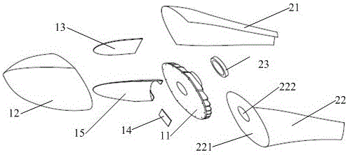
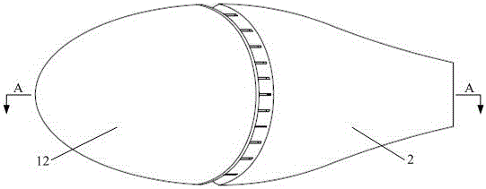
[0036] See attached figure 1 to attach Figure 6 As shown, a multi-cavity LED street lamp includes a front end cover 1 and a rear end cover 2, the front end cover 1 is connected to the rear end cover 2, and the front end cover 1 and the rear end cover 2 each form an independent cavity; The front cover 1 includes a front cover 11 and an LED lens 12, the LED lens 12 is fixed on the front cover 11 to form a closed cavity, and the cavity formed by the LED lens 12 and the front cover 11 is provided with a PCB board 13 and LED light source 14; the front cover 11 is placed obliquely, forming an angle with the horizontal plane, and the rear end cover 2 is fixed on the front cover 11.

[0037] Further, the angle formed by the front cover 11 and the horizontal plane is 0°-40°.

[0038] Further, a reflector 15 is provided in the cavity formed by the LED lens 12 and the front cover 11 , and the reflector 15 is embedded in the LED lens 12 . The LED lens 12 has a large optical cavity, an...

Embodiment 2

[0048] See attached Figure 6 to attach Figure 11 As shown, a multi-cavity LED street lamp includes a front end cover 1 and a rear end cover 2, the front end cover 1 is connected to the rear end cover 2, and the front end cover 1 and the rear end cover 2 each form an independent cavity; The front cover 1 includes a front cover 11 and an LED lens 12, the LED lens 12 is fixed on the front cover 11 to form a closed cavity, and the cavity formed by the LED lens 12 and the front cover 11 is provided with a PCB board 13 and LED light source 14; the front cover 11 is placed obliquely, forming an angle with the horizontal plane, and the rear end cover 2 is fixed on the front cover 11.

[0049] Further, the angle formed by the front cover 11 and the horizontal plane is 0°-40°.

[0050] Further, a reflector 15 is provided in the cavity formed by the LED lens 12 and the front cover 11 , and the reflector 15 is embedded in the LED lens 12 . The LED lens 12 has a large optical cavity, ...


PUM


Abstract

The invention discloses a multi-cavity LED street lamp. The multi-cavity LED street lamp comprises a front end cover and a rear end cover which are connected, wherein an independent cavity is formed in each of the front end cover and the rear end cover; the front end cover comprises a front cover and an LED lens, the LED lens is fixed on the front cover to form a closed cavity, and a PCB (printed circuit board) and an LED light source are arranged in the cavity formed by the LED lens and the front cover; the front cover is obliquely arranged to form an included angle with the horizontal plane, and the rear end cover is fixed on the front cover. According to the multi-cavity LED street lamp, the LED light source is obliquely mounted, most of outgoing light of the LED light source is irradiated to a street, the light energy utilization rate of the lamp is greatly increased, the light distribution efficiency is improved, and the optimal illumination is realized. With the adoption of high-voltage, linear and constant-current drive, an addition power supply is not required, the product size and the cost are greatly reduced, and the miniaturization design of the product is facilitated.

Description

technical field [0001] The invention belongs to the technical field of semiconductor lighting, and in particular relates to a multi-cavity LED street lamp. Background technique [0002] In recent years, due to the development of LED technology, LED lighting has begun to be recognized and adopted by most users. Various LED lamps emerge in an endless stream, and the structure of LED lamps is also diverse. [0003] However, most of the LED light sources in the existing LED street lamps are installed horizontally and irradiate vertically downward. Part of the light emitted by the LED light source is irradiated on the road, and some is irradiated on the side of the house. The light energy irradiated on the side of the house is not fully utilized, resulting in a low light energy utilization rate of the existing LED lamps, and is prone to glare. [0004] Moreover, the existing LED street lamps usually consist of a plurality of LED light source modules, and each LED light source mo...

Claims


Application Information

Patent Timeline
Patent Type & Authority Applications(China)
IPC IPC(8): F21V19/00F21V5/04F21V7/00F21V23/00F21Y115/10F21W131/103
CPCF21V5/04F21V7/00F21V19/001F21V23/003F21W2131/103
Inventor 张志海胡俊曾平吴新慧
Owner JIANGXI GENERAL ENERGY SAVING TECH
Why Eureka
Try Eureka