Tunnel type dryer based on drying effect

A tunnel dryer and drying technology, which is applied in the direction of dryers, progressive dryers, drying, etc., can solve the problem that the drying effect cannot be balanced with the uniformity of the drying hot air flow, and achieve the purpose of improving the drying and sterilization effect, The effect of improving the utilization rate and improving the import speed

Inactive Publication Date: 2017-01-04
CHENGDU OLYMVAX BIOPHARM
View PDF6 Cites 3 Cited by
  • Summary
  • Abstract
  • Description
  • Claims
  • Application Information

AI Technical Summary

Problems solved by technology

[0005] The purpose of the present invention is to provide a tunnel dryer based on the drying effect, which solves the problem that the drying effect of the existing tunnel dryer and the dispersion uniformity of the drying hot air flow cannot be taken into account. In addition, the present invention can also effectively improve the drying heat. Airflow introduction speed

Method used


Image

  • Tunnel type dryer based on drying effect
  • Tunnel type dryer based on drying effect
  • Tunnel type dryer based on drying effect

Examples


Embodiment 1

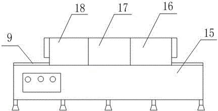
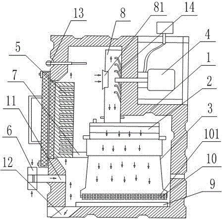
[0041] Such as Figure 1 to Figure 3 As shown, the tunnel dryer based on the drying effect includes a bracket 15, the upper end of the bracket 15 is provided with a conveying mechanism 9, and the bracket 15 is sequentially provided with a preheating device 16, a sterilizing device 17 and Cooling device 18, the sterilizing device 17 includes a housing 1, the housing 1 is provided with an air inlet 11, an air outlet 12, a conveying mechanism 9 is arranged below the inside of the housing 1, and the inside of the housing 1 is arranged above the air inlet 11 There is a heating device 5, and the inside of the housing 1 is provided with an air collecting tube 8, the side wall of the air collecting tube 8 is provided with an air inlet 81 that cooperates with the heating device 5, and the housing 1 is provided with a heating layer that cooperates with the air collecting tube 8 Air flow fan 4, the lower end of described air gathering cylinder 8 is provided with second filter 2, and the ...

Embodiment 2

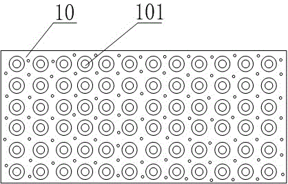
[0043] Such as Figure 1 to Figure 3As shown, this embodiment is based on Embodiment 1, the air inlet 11 is provided with a first filter 6; the housing 1 is provided with a temperature sensing device 13 at the air outlet of the heating device 5, and the temperature sensing Device 13 is a temperature sensor, and can also be a thermocouple; a baffle plate 7 is arranged between the heating device 5 and the wind gathering hood 3; the inner diameter of the wind gathering tube 8 is less than the inner diameter of the wind gathering hood 3; The inner diameter of 101 gradually increases from the middle to both ends; the inner diameter of the port of the ventilation pipe 101 is 4mm.


PUM


Abstract

The invention discloses a tunnel type dryer based on drying effect. The tunnel type dryer based on the drying effect comprises a support, wherein a conveying mechanism is arranged at the upper end of the support, a preheating device, a sterilizing device and a cooling device are sequentially arranged along the moving direction of the conveying mechanism on the support, the sterilizing device comprises a shell, the conveying mechanism is arranged below the interior of the shell, the heating device is arranged above an air inlet of the interior of the shell, an air gathering drum is arranged inside the shell, an air inlet vent matched with the heating device is formed in the side wall of the air gathering drum, and a heating laminar flow fan matched with the air gathering drum is arranged on the shell; a connecting plate is arranged at an air outlet end of the air gathering cover, a plurality of ventilation pipes are vertically arranged on the connecting plate, and ventilation holes are formed between adjacent ventilation pipes on the connecting plate; and multiple deflectors are arranged at one side, opposite to the air inlet vent, in the air gathering drum. The tunnel type dryer disclosed by the invention can be used for solving the problem that drying effect of an existing drying system and dispersion uniformity of drying hot air flow dispersion can not be balanced, and speed of introducing drying hot air flow can be effectively improved.

Description

technical field [0001] The invention relates to the technical field of drying and sterilization, in particular to a tunnel dryer based on drying effect. Background technique [0002] Tunnel dryer is mainly used to seal the container bottles continuously conveyed in the tunnel and preheat, dry, sterilize and cool them. Preheating is carried out in the preheating system, drying and sterilization are carried out in the same drying system, and cooling is carried out in the cooling system. [0003] The drying system mainly introduces the external air into the closed space for heating, and the heated dry hot air enters the filter device for filtration under the action of the heating laminar flow fan, and the filtered hot air is used for drying the containers and bottles passing through the drying system. Dry and sterilize. [0004] Existing tunnel dryers are prone to problems such as uneven dispersion of the drying hot air flow or poor drying effect. Contents of the invention ...

Claims


Application Information

Patent Timeline
Patent Type & Authority Applications(China)
IPC IPC(8): F26B15/00F26B21/00A61L2/20
CPCF26B15/00A61L2/20F26B21/001
Inventor 张强何静李成
Owner CHENGDU OLYMVAX BIOPHARM
Why Eureka
Try Eureka