

Curve vehicle location device and method
A technology for vehicle positioning and curves, applied in the computer field
- Summary
- Abstract
- Description
- Claims
- Application Information
AI Technical Summary
Problems solved by technology
Method used
Image

Examples
Embodiment 1
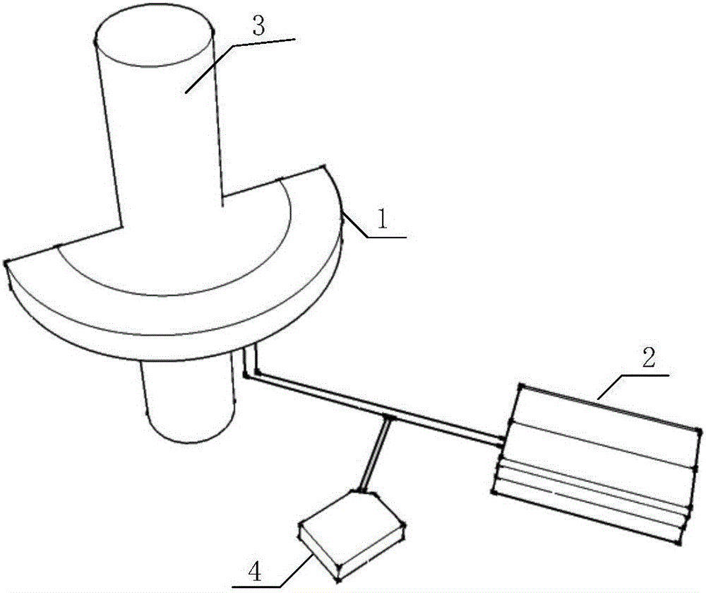
[0093] figure 2 It is a schematic structural diagram of a curved vehicle positioning device provided in Embodiment 1 of the present invention, as shown in figure 2 As shown, the device includes: a laser scanning unit 1 and a central processing unit 2;
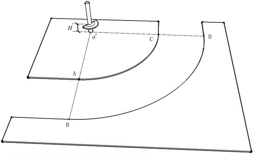
[0094] The laser scanning unit 1 is fixed on the installation pole 2, and is located at the center point inside the curve or the extension line outside the radius of the curve at a preset distance from the lane boundary line, and is used for real-time acquisition of ranging waveforms in the curve area. Wherein, when the laser scanning unit 1 is located at the center point inside the curve, such as image 3 As shown; when the laser scanning unit 1 is located at the preset distance Dis from the extension line outside the radius of the curve to the lane boundary line, as Figure 4 shown.
[0095] The central processing unit 2 is connected to the laser scanning unit 1, and is used to receive the curve area ranging waveform sen...
Embodiment 2
[0103] Figure 5 It is a schematic flow chart of a curve vehicle positioning method provided by the present invention, such as Figure 5 As shown, the curve vehicle positioning method includes the following steps:
[0104] S1: The laser scanning unit collects the ranging waveform in the curve area in real time.
[0105] For example, the ranging waveform in the curve area is as follows Image 6 shown.
[0106] S2: The central processing unit receives the ranging waveform in the curve area sent by the laser scanning unit, and performs coordinate conversion, interference elimination and area search on the ranging waveform of the current frame, and determines the position information of the scanning point corresponding to the vehicle area of the current frame;
[0107] S3: The central processing unit performs area matching on the vehicle area of the current frame and the vehicle area of the previous frame, and determines that the vehicle area of the current frame corres...
Embodiment 3
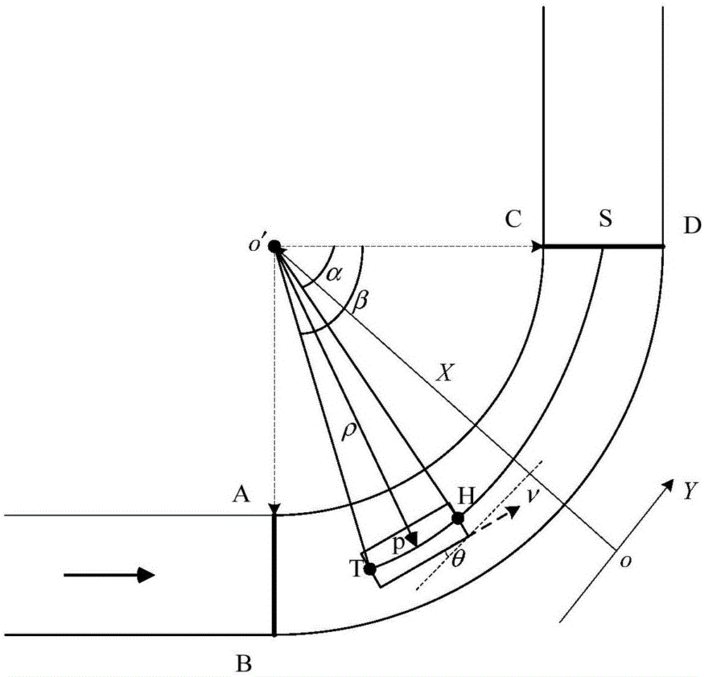
[0163] In this example, if Figure 12 As shown, the curve vehicle positioning device is installed at a preset distance from the extension line outside the curve radius to the lane boundary line. Among them, the radius of the arc segment near the center of the curve R 1 =10000mm, the radius R of the arc section of the boundary of the far center of the curve 2 =14000mm, the angle Q between the starting point of the curve and the line where the center of the inner circle of the curve is located and the radius of the ox axis 1 =-45°, the angle Q between the end point of the curve and the line where the center of the inner circle of the curve is located and the radius of the ox axis 2 = 45°.
[0164] Among them, the curved vehicle positioning device includes: a laser scanning unit 1, a central processing unit 2, a mounting pole 3 and a power supply unit 4. The laser scanning unit 1 is fixed on the mounting pole 3, and is located outside the radius of the curve. At the distance ...
PUM
 Abstract
Description
Claims
Application Information