
Auxiliary power switching device and method thereof

A switching device and auxiliary power supply technology, which is applied in the direction of measuring device, data processing power supply, measurement flow/mass flow, etc., can solve the problems of system shutdown, voltage drop, auxiliary power supply oscillation instability, etc., and achieve the effect of avoiding oscillation instability

Active Publication Date: 2019-03-01
KUNDA COMP TECHKUSN +1
View PDF5 Cites 0 Cited by
  • Summary
  • Abstract
  • Description
  • Claims
  • Application Information

AI Technical Summary

Problems solved by technology

However, if the voltage switching between the two input power supplies, the main power supply and the backup power supply is not good, the output auxiliary power supply will fluctuate and become unstable, and even have a large voltage drop, causing the system to shut down

Method used


Image

  • Auxiliary power switching device and method thereof
  • Auxiliary power switching device and method thereof
  • Auxiliary power switching device and method thereof

Examples


Embodiment Construction

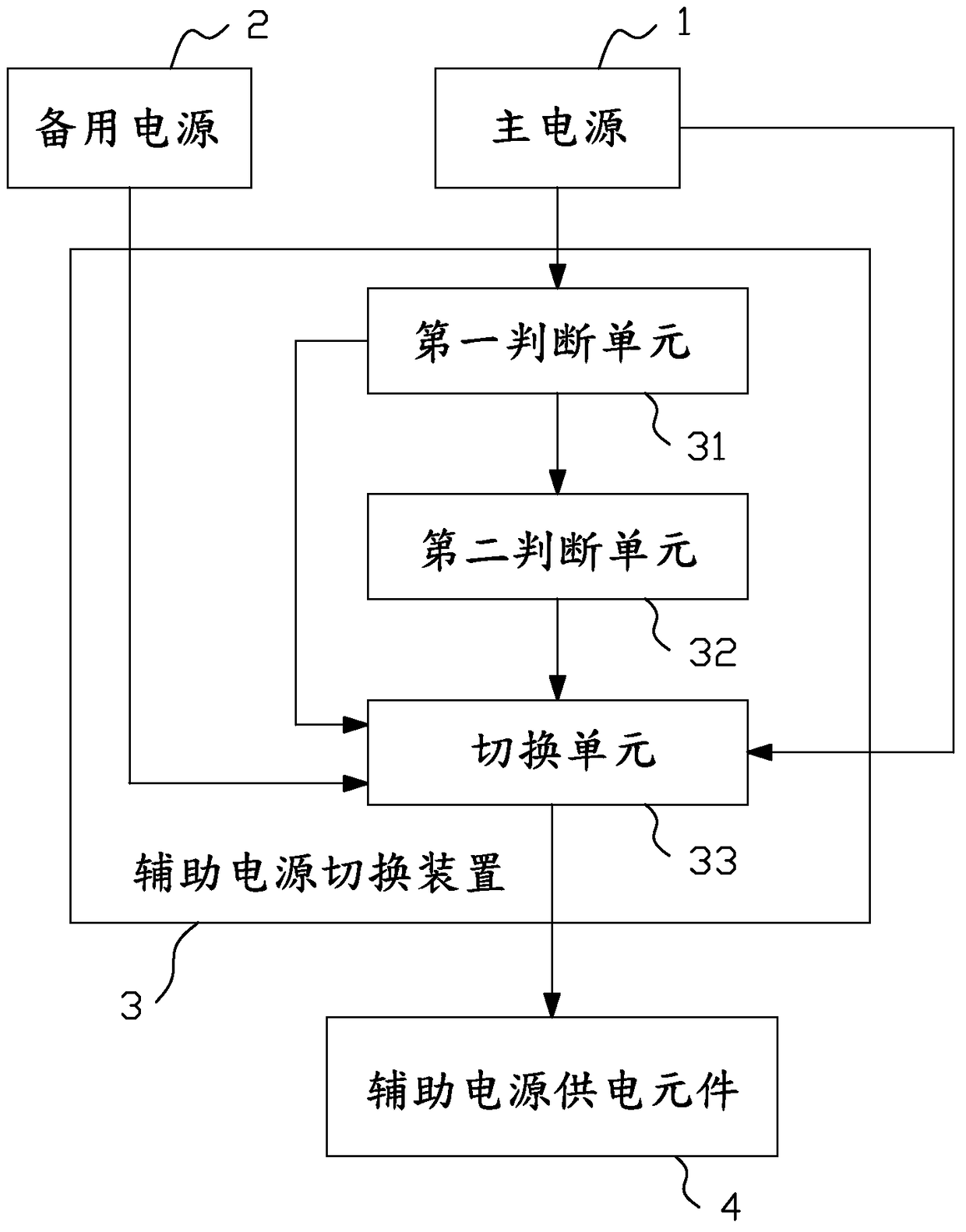
[0015] see figure 1 As shown, the auxiliary power switching device 3 of the present invention is connected to the main power supply 1, the backup power supply 2 and the auxiliary power supply element 4 for timely switching the main power supply 1 or the backup power supply 2 to provide stable and effective power supply for the auxiliary power supply element 4. auxiliary voltage. The main power supply 1 is used to provide a first voltage. The backup power supply 2 is used to provide the second voltage. In this embodiment, the auxiliary power switching device 3 includes a first judging unit 31, a second judging unit 32, and a switching unit 33. The first judging unit 31 is connected to the main power supply 1 for judging the main power supply. Whether the first voltage of 1 is greater than or equal to a preset value, the second judging unit 32 is connected to the first judging unit 31 for when the first judging unit 31 judges to know the first voltage of the main power supply ...


PUM


Abstract

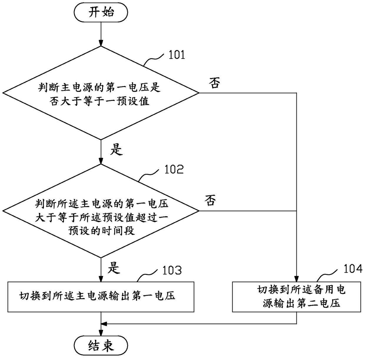
The invention provides an auxiliary power switching device and a method thereof. The method is realized through the auxiliary power switching device. The auxiliary power switching device is connected with a main power, a standby power and an auxiliary power supply component for duly switching the main power and the standby power. The auxiliary power switching device comprises a first judgment unit, a second judgment unit and a switching unit. The auxiliary power switching method comprises the following steps of: a: judging whether the first voltage of the main power is greater than or equal to a preset value or not by the first judgment unit, executing a step b if the first voltage of the main power is greater than or equal to the preset value, and otherwise, executing a step d; b: judging whether the first voltage of the main power is greater than or equal to a preset time period or not by the second judgment unit, executing a step c if the first voltage of the main power is greater than or equal to the preset time period, and otherwise, executing a step d; c: switching to the main power by the switching unit to output first voltage; and d: switching to the standby power by the switching unit to output second voltage.

Description

technical field [0001] The invention relates to an auxiliary power switching device and a method thereof. Background technique [0002] The power supply of the server will supply main power (main power) and backup power (standy power). As the name suggests, the backup power supply is the power supply when the board is in standby and waiting for the board to work. The board will wait for the user to press the power switch, turn on the main power supply, and perform a series of tasks. Because the board will not draw a large current in the standby state, so in the design of the power supply of the server, the power supply of the backup power supply is much smaller than that of the main power supply. Because the power supply of the power supply is uneven, we will use the main power supply that can provide a large current as the auxiliary power supply, and its output is named auxiliary power supply (auxiliarypower). In other words, the auxiliary power supply has two stages of ...

Claims


Application Information

Patent Timeline
Patent Type & Authority Patents(China)
IPC IPC(8): G06F1/26G06F1/30
Inventor 罗维毅
Owner KUNDA COMP TECHKUSN
Learn More